Hydraulic control valve for a longitudinally adjustable connecting rod with an end-face control piston

a technology of hydraulic control valve and connecting rod, which is applied in the direction of valve operating means/release devices, machines/engines, mechanical equipment, etc., can solve the problems of unintentional spontaneous ignition of the piston engine, component damage in the engine, and the spark ignition engine not running smoothly, so as to reduce the installation space required for the control valve, increase the operational reliability, and reduce the production cost

Active Publication Date: 2022-11-01
IWIS MOTORSYSTEME GMBH & CO KG +1
View PDF18 Cites 0 Cited by
  • Summary
  • Abstract
  • Description
  • Claims
  • Application Information

AI Technical Summary

Benefits of technology

[0016]The at least two outlet valves can advantageously be actuated alternately by the control slide. This enables the reliable operation of the hydraulic control device with the associated pressure chambers emptying alternately or the second other pressure chamber filling, respectively, as well as the secure positioning of the connecting rod in the longitudinal position that is set.
[0017]A preferred embodiment provides that the hydraulic control device comprises a return spring for retaining the control slide in a first initial position or to return it to the first initial position, where the return spring is preferably arranged around the control slide. The return spring makes it possible to provide two different switching positions in the hydraulic control valve without providing an active return mechanism, additional pressure chambers, or supply lines. As a result, the production costs can be kept low, while simultaneously increasing in operational reliability. Furthermore, such a return spring can be adapted in a simple manner to different control pressures or applications of the control valve without having to change the entire configuration of the hydraulic control device or even of the longitudinally adjustable connecting rod. The arrangement of the return spring around the control slide reduces the installation space required for the control valve and, at the same time, also reduces manufacturing costs. Alternatively, the return spring can also be arranged between the control piston and the face end of the control cylinder, for example, of a cylinder cover.
[0018]A special variant provides that the control slide be arranged inclined relative to the longitudinal direction of the connecting rod and inclined to the normal to the longitudinal direction of the connecting rod, preferably at an angle between 15° and 75°. The inclined arrangement of the control slide relative to the longitudinal direction of the connecting rod and relative to the normal to the longitudinal direction of the connecting rod can compensate for or at least reduce the negative influences of the inertia of the hydraulic fluid in the hydraulic fluid ducts and the components of the hydraulic control device, if the angle has been selected to be favorable. As a result, faults and malfunctions in the activation of the control device can be avoided. Furthermore, the inclined arrangement of the control slide also minimizes disruptive influences upon the other components of the hydraulic control device and the longitudinally adjustable connecting rod, the function of which can be impaired, in particular by the mass forces that increase sharply at high rotational speeds.
[0019]One embodiment of the longitudinally adjustable connecting rod provides that two connecting rod members be provided, where the first connecting rod member comprises the first connecting rod end and where the second connecting rod member comprises the second connecting rod end, and where the first connecting rod member is movable, is preferably telescopically movable, relative to the second connecting rod member in the longitudinal direction of the connecting rod for adjusting the distance between the piston pin and the crankshaft journal. In contrast to connecting rods with eccentrics, two connecting rod members that can be moved relati

Problems solved by technology

The thermal efficiency increases as the compression ratio rises, but too high a compression ratio can lead to unintentional spontaneous ignition of the piston engine.
This early combustion does not only lead to spark ignition engines not running smoothly and so-called knocking of the engine, but can also lead to component damage in the engine.
In particular in the development of modern piston engines, the installation space for such connecting rods is limited both in the longitudinal direction of the connecting rod (axially)

Method used


Image

  • Hydraulic control valve for a longitudinally adjustable connecting rod with an end-face control piston
  • Hydraulic control valve for a longitudinally adjustable connecting rod with an end-face control piston
  • Hydraulic control valve for a longitudinally adjustable connecting rod with an end-face control piston

Examples


Embodiment Construction

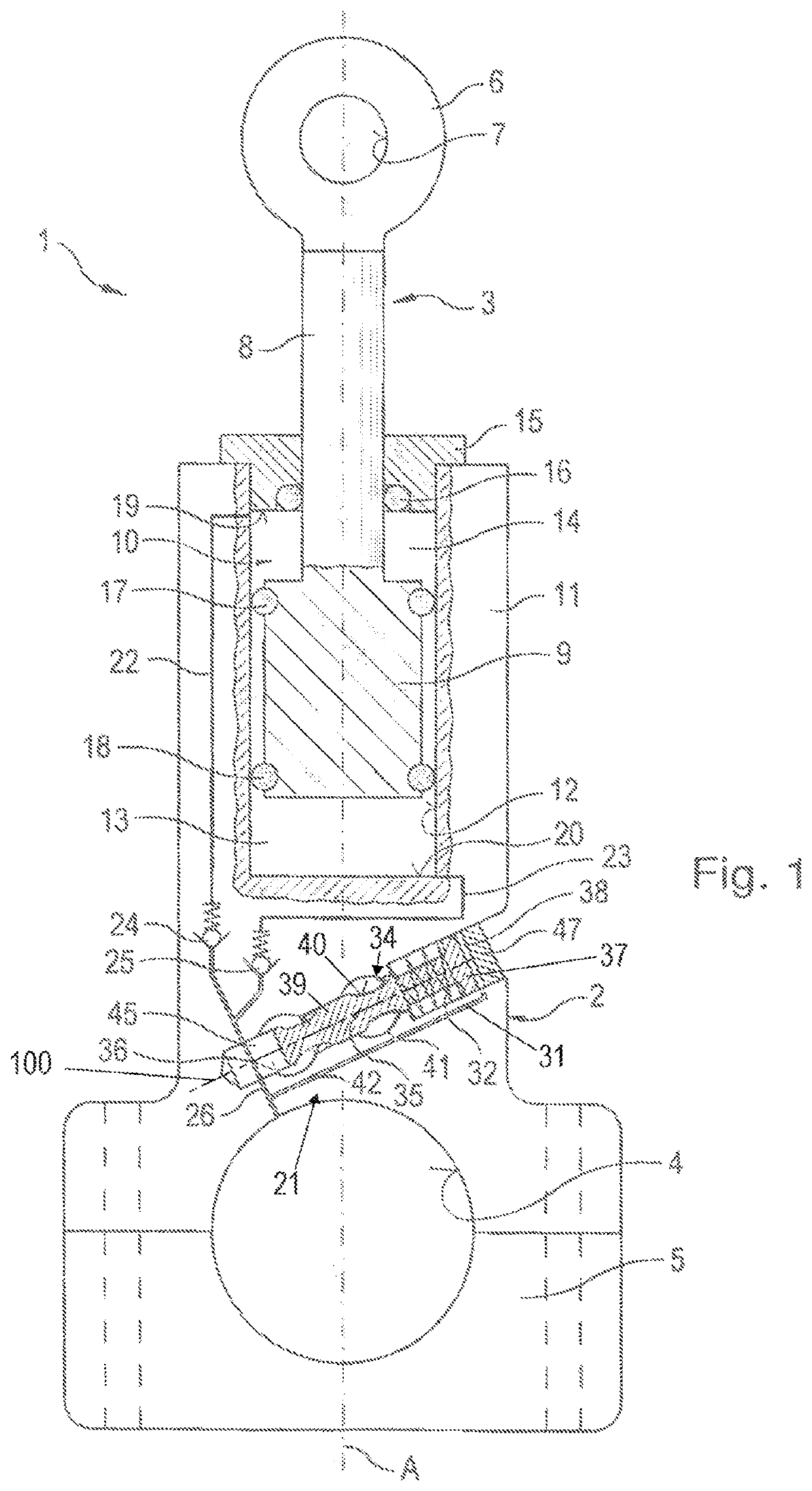
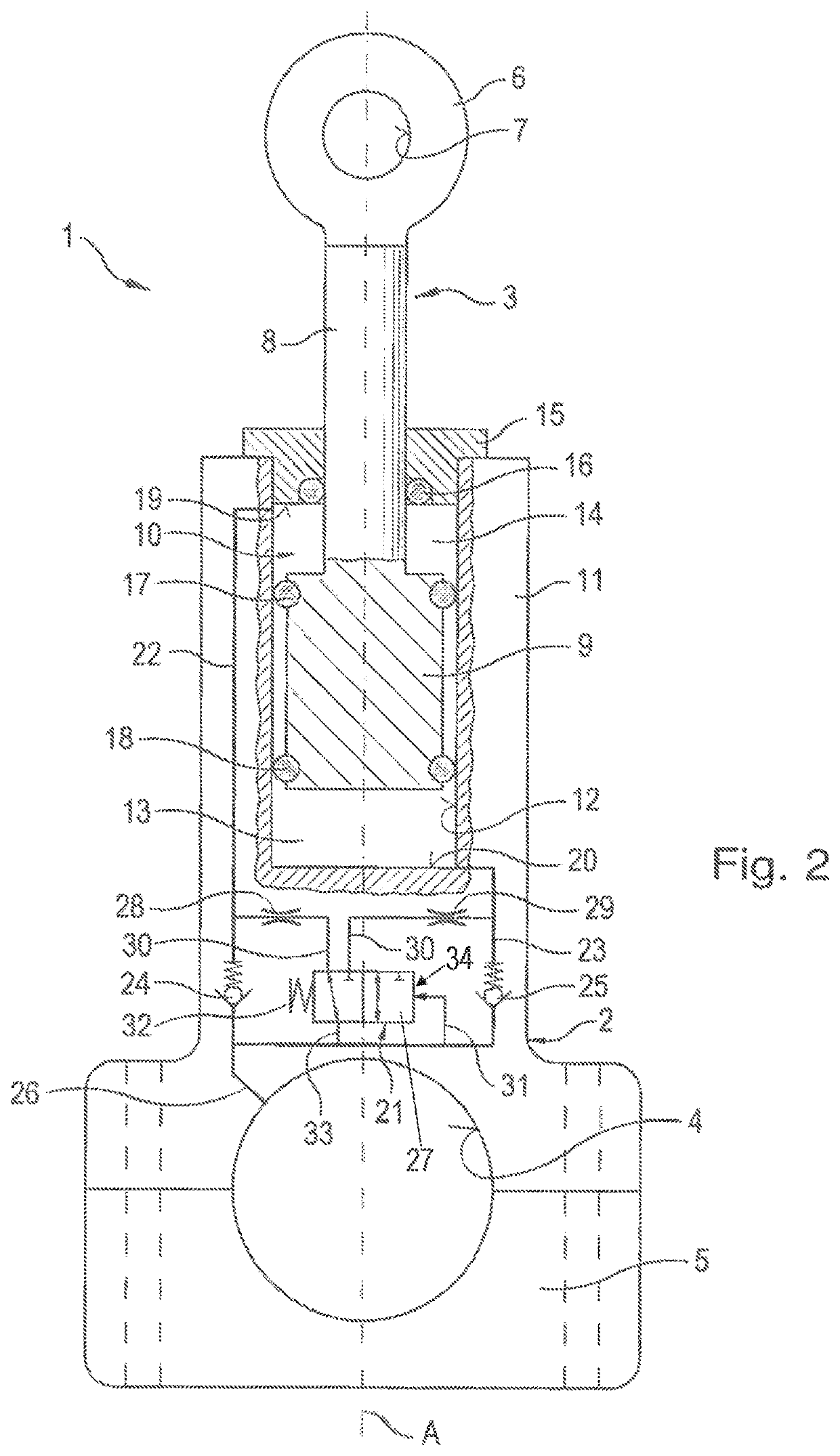
[0029]Longitudinally adjustable connecting rod 1 shown in the schematic view in FIG. 1 comprises two connecting rod members 2, 3 telescopically movable relative to one another. Lower connecting rod member 2, which is arranged at the bottom in the illustration of longitudinally adjustable connecting rod 1 in FIG. 1, comprises a connecting rod large end 4 with which longitudinally adjustable connecting rod 1 is mounted on the crankshaft (not shown) of the piston engine. For this purpose, a bearing shell 5 is further arranged on lower connecting rod member 2 and together with the lower region of lower connecting rod 2, which is also configured like a bearing shell, forms connecting rod large end 4. Bearing shell 5 and lower connecting rod member 2 are connected to one another by way of connecting rod screws (shown schematically as dashed lines). Upper connecting rod member 3 comprises a connecting rod head 6 with a connecting rod small end 7 which receives the piston pin (not shown) of...


PUM


Abstract

A longitudinally adjustable connecting rod for a piston engine, where the connecting rod includes a first connecting rod end for receiving a piston pin and a second connecting rod end for receiving a crankshaft journal, where the distance between the piston pin and the crankshaft journal is adjustable in the longitudinal direction (A) of the connecting rod by way of a hydraulic control device with a hydraulic control valve. The hydraulic control valve comprises a control cylinder and a control slide which is guided in a slidable manner in the control cylinder and which can be pressurized, and at least one outlet valve which can be actuated by the control slide. The control slide comprises a control piston which is arranged on the end face, with a control pressure surface which can be subjected to the hydraulic control pressure and which defines a control pressure chamber in the control cylinder. The use of such a longitudinally adjustable connecting rod with a hydraulic control device in a piston engine as well as a corresponding piston engine is also provided.

Description

CROSS-REFERENCE TO RELATED APPLICATIONS[0001]This application is a National Stage of International patent application PCT / AT2019 / 060335, filed on Oct. 8, 2019, which claims priority to foreign Austrian patent application No. AT A50871 / 2018, filed on Oct. 8, 2018, the disclosures of which are incorporated by reference in their entirety.FIELD OF THE INVENTION[0002]The present invention relates to a longitudinally adjustable connecting rod for a piston engine, where the connecting rod comprises a first connecting rod end for receiving a piston pin and a second connecting rod end for receiving a crankshaft journal, where the distance between the piston pin and the crankshaft journal is adjustable in the longitudinal direction of the connecting rod by way of a hydraulic control device, and where the hydraulic control device comprises a control cylinder and a control slide which is guided in a slidable manner in the control cylinder and which can be pressurized. The invention further rela...

Claims


Application Information

Patent Timeline
IPC IPC(8): F02B75/04
CPCF02B75/045F16C7/06F02D15/02F16K31/12F16K31/44F16K31/52425F16K31/52416
Inventor HELLER, MALTEARENS, KAIRIBA, ZOLTÁNBODENSTEINER, MARTINLATZ, STEFFENKOMETTER, BERNHARDMELDE-TUCZAI, HELMUT
Owner IWIS MOTORSYSTEME GMBH & CO KG
Why Eureka
Try Eureka