Headphone

a technology for headphones and earphones, applied in the field of headphones, can solve the problems of passive transmission of external noise through the opening, inability to solve the reduction in degradation of the sound quality contrary to expectations, so as to prevent the reduction of the volume of the front air chamber, maintain the volume, and improve the sound quality

Inactive Publication Date: 2011-08-04
AUDIO-TECHNICA
View PDF5 Cites 17 Cited by
  • Summary
  • Abstract
  • Description
  • Claims
  • Application Information

AI Technical Summary

Benefits of technology

[0013]An object of the present invention, which has been accomplished to solve such problems, is to provide a headphone including a plurality of buffers having a predetermined rigidity between an ear pad and a baffle plate, and thereby capable of preventing a reduction in volume of a front air chamber caused by lateral pressure to improve quality of sound in low to medium frequency bands.
[0014]The present invention relates to a headphone including a headband, an ear cup attached to the headband, a baffle plate fixed to the ear cup and having a rib wall at its periphery, an ear pad engaged with the baffle plate, and gas-permeable buffers between the ear cup and the baffle plate, wherein the buffers and the rib wall prevent a reduction in volume of a front air chamber caused by lateral pressure.
[0022]The headphone of the present invention includes the buffer having a predetermined thickness provided between the front face of the baffle plate and the ear pad, and can prevent a reduction in volume of the front air chamber due to compression of the ear pad caused by lateral pressure of the headband, and thus can maintain the volume of the front air chamber which is especially effective for improving the quality of sound in low to medium frequency bands. The headphone of the present invention includes a plurality of buffers having different rigidities and can surely prevent a reduction in volume of the front air chamber caused by lateral pressure of the headband, maintaining a sufficient volume of front air chamber to improve quality of sound in low to medium frequency bands. The use of gas-permeable buffers can maintain a larger volume of front air chamber.

Problems solved by technology

The headphone disclosed in Japanese Unexamined Patent Application Publication No. 2009-17176 also maintains the volume of the front air chamber by the thickness of the ear pad and thus does not solve the reduction in volume of the front air chamber caused by lateral pressure.
The opening of the ear pad, however, causes passive transmission of external noise through the opening.
This leads to drastic changes in sound insulation characteristics of specific frequencies, resulting in the degradation in quality of sound contrary to expectation.

Method used


Image

  • Headphone
  • Headphone
  • Headphone

Examples


first embodiment

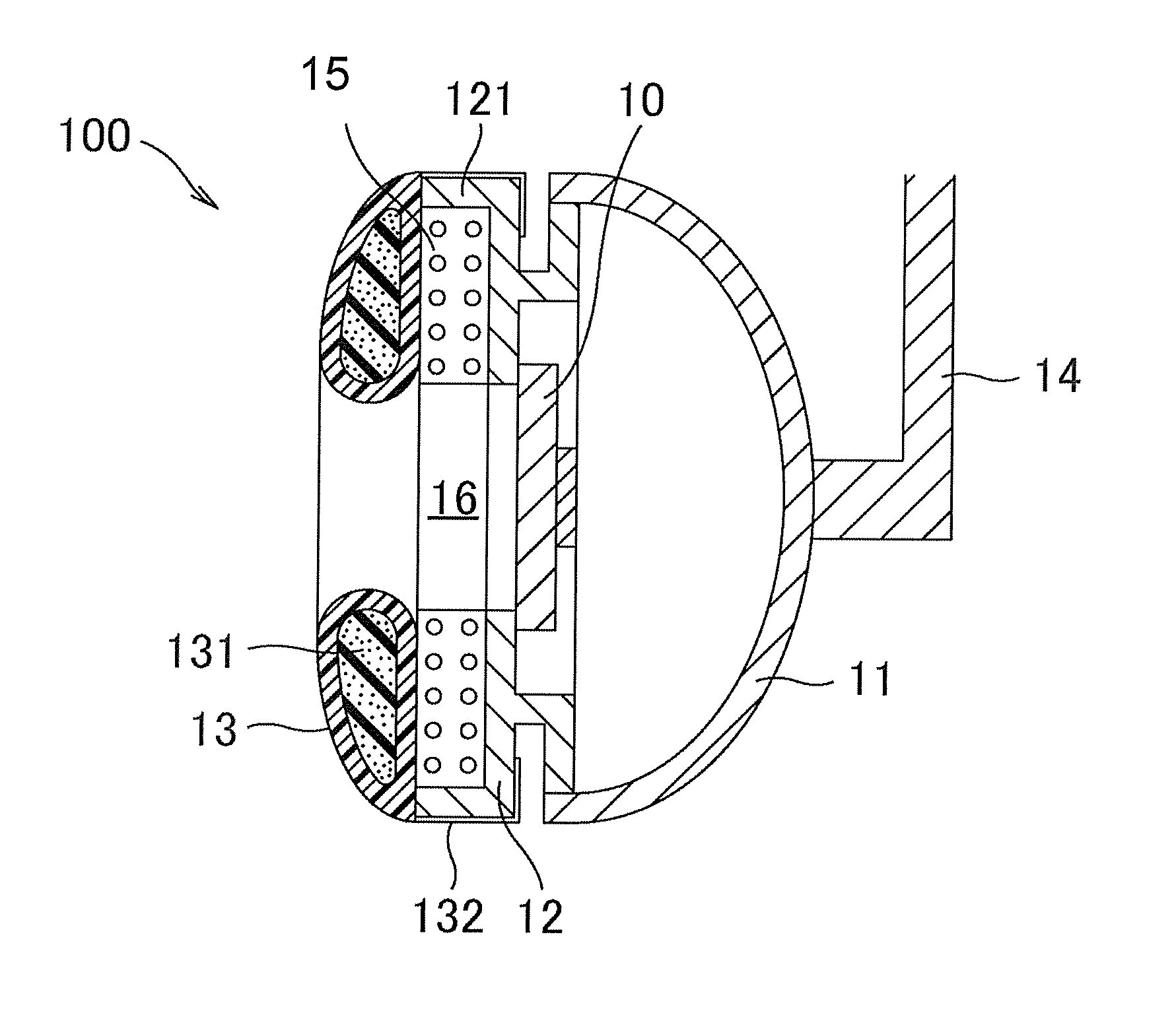
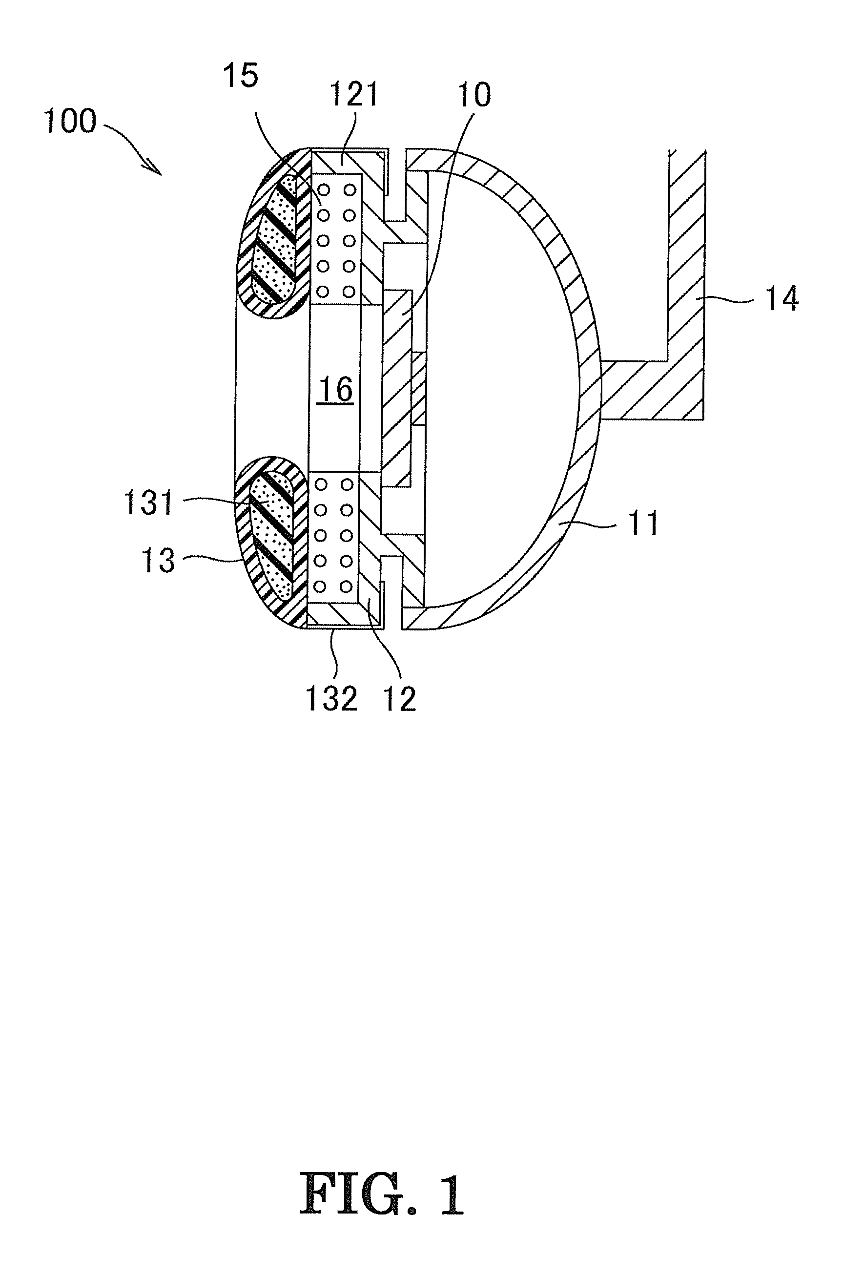
[0027]An embodiment of a headphone in accordance with the present invention will now be described with reference to the attached drawings. FIG. 1 is a longitudinal sectional-view of an exemplary headphone of the present invention. The headphone 100 includes a baffle plate 12 fixed to the opening of an ear cup 11, and an ear pad 13 engaged with the front face of the baffle plate 12 (left in FIG. 1).

[0028]The headphone 100 further includes a speaker unit 10 behind the baffle plate 12 that outputs audible signals. The speaker unit 10 reproduces musical sound from musical sound signals input from a sound source (not shown) and outputs the musical sound toward the front air chamber.

[0029]The baffle plate 12 is a disk having a central opening and has a disk flange having a central opening and a cylindrical rib protruding from the baffle palate 12. The baffle plate 12 and the flange have different outer diameters. The baffle plate 12, the flange, and the cylindrical rib define a groove ove...

second embodiment

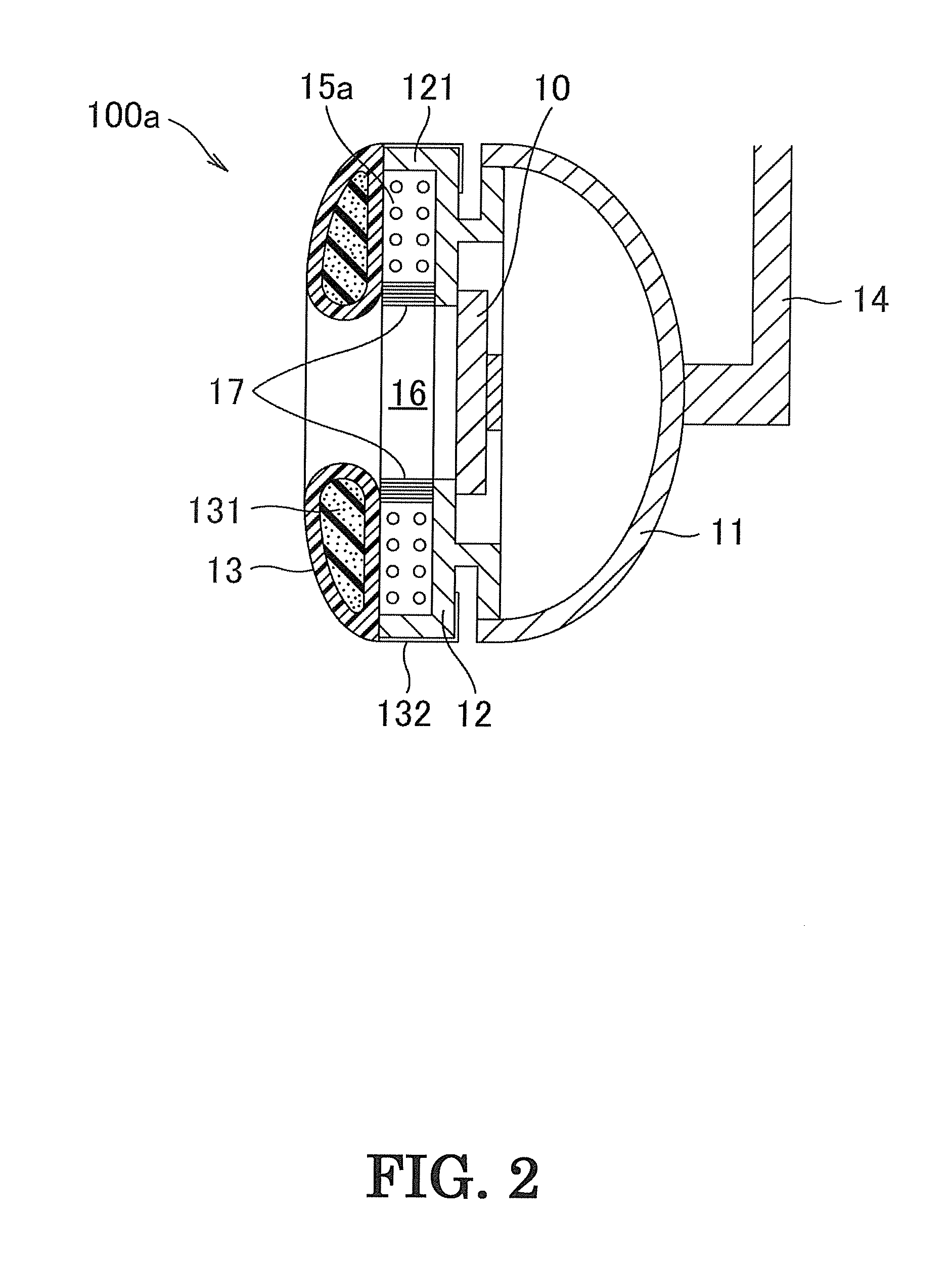
[0036]Another embodiment of the headphone in accordance with the present invention will now be described with reference to FIG. 2. As in the headphone 100 described in the first embodiment, a headphone 100a illustrated in FIG. 2 includes a buffer 15a provided between a baffle plate 12 having a rib wall 121, and an ear pad 13 engaged such that a engaging portion covers the outer circumference of the baffle plate 12.

[0037]A buffer 17 having gas permeability and a higher rigidity than the buffer 15a is disposed to the inner circumference of the buffer 15a. The buffer 17 and the buffer 15a may be integrated by welding or bonding. These members may each be fixed to the baffle plate 12 or the ear pad 13.

[0038]The headphone 100a fixed on a user's head can maintain a sufficient volume of front air chamber 16 without a reduction in volume of the chamber by the rigidity of the rib wall 121 of the baffle plate 12 and the buffer 17 even if the ear pad 13 is compressed by lateral pressure caused...

third embodiment

[0043]Another embodiment of the headphone in accordance with the present invention will now be described with reference to FIG. 3. A headphone 100b includes a baffle plate 12a fixed to an opening of an ear cup 11, and an ear pad 13 engaged with the front face of the baffle plate 12a (left in FIG. 3).

[0044]The headphone 100b further includes a speaker unit 10 behind the baffle plate 12a that outputs audible signals. The speaker unit 10 reproduces musical sound from musical sound signals input from a sound source (not shown) and outputs the musical sound toward the front air chamber.

[0045]The baffle plate 12a is a disk having a central opening and has a disk flange having a central opening and a cylindrical rib protruding from the baffle plate 12a. The baffle plate 12a and the flange have different outer diameters.

[0046]The ear pad 13 includes a toroidal cushion 131 and a skin covering the toroidal cushion 131, the skin having an extending engaging portion 132. The engaging portion 13...


PUM


Abstract

A headphone including a headband, an ear cup attached to the headband, a baffle plate fixed to the ear cup and having a rib wall at its periphery, an ear pad engaged with the baffle plate, and a gas permeable buffer between the ear cup and the baffle plate, wherein the buffer and the rib wall prevent a reduction in volume of a front air chamber caused by lateral pressure.

Description

TECHNICAL FIELD[0001]The present invention relates to a headphone that includes a buffer provided between a baffle plate and an ear pad, that can prevent a reduction in volume of a front air chamber caused by lateral pressure, and that exhibits improved quality of sound in low to medium frequency bands.BACKGROUND ART[0002]A closed headphone of which an ear pad is tightly put into close contact with user's ear auricle and its periphery, can highly insulate the user from ambient noise and prevent sound from leaking to the exterior. Furthermore, a closed space defined by the ear pad provides a large volume of front air chamber, which is a space in front of the baffle plate and in communication with an ear canal. The space improves the quality of reproduced sound in low to medium frequency bands.[0003]The structure of a typical conventional headphone is explained with reference to a longitudinal sectional-view in FIG. 4. The headphone 60 includes a front air chamber 64 that is a space d...

Claims


Application Information

Patent Timeline
Patent Type & Authority Applications(United States)
IPC IPC(8): H04R1/10
CPCH04R1/10H04R1/1008H04R1/2803
Inventor KIMURA, TOMINORI
Owner AUDIO-TECHNICA
Why Eureka
Try Eureka