
Method and apparatus for determining location of user equipment in a communication system

a communication system and user equipment technology, applied in the direction of receiving monitoring, location information based service, instruments, etc., can solve the problems of inability of the rrh to provide a service to the ue, and it is difficult to accurately determine the location of the ue that is within the service area of the rrh

Active Publication Date: 2011-08-04
SAMSUNG ELECTRONICS CO LTD
View PDF11 Cites 146 Cited by
  • Summary
  • Abstract
  • Description
  • Claims
  • Application Information

AI Technical Summary

Problems solved by technology

However, when a BS is connected to a plurality of Remote Radio Heads (RRHs) to extend the service area of the BS, an RRH that is providing a service to a UE cannot be identified only based on the location of the BS.
Therefore, it is difficult to accurately determine the location of the UE that is within the service area of the RRH.

Method used


Image

  • Method and apparatus for determining location of user equipment in a communication system
  • Method and apparatus for determining location of user equipment in a communication system
  • Method and apparatus for determining location of user equipment in a communication system

Examples


first embodiment

[0032]The method for determining the location of a UE that initially accesses a BS according to the present invention will first be described. Herein, an embodiment in which a plurality of UEs initially access a BS will be taken as an example.

[0033]UEs transmit PRACH signals to a BS which they intend to initially access. In general, a PRACH is a physical channel on which a BS receives a preamble sequence from a UE to acquire synchronization with the UE. To use the PRACH, the BS transmits PRACH configuration information to UEs in System Information Block (SIB)-2 or a Radio Resource Control (RRC) message. The PRACH configuration information indicates the position of a frequency at which the UE is supposed to transmit the preamble sequence and the format of the preamble sequence. For example, the PRACH configuration information includes Prach-ConfigInfo [6 bits], rootSequenceIndex [10 bits], zeroCorrelationZoneConfig [4 bits], and high-SpeedFlag [1 bit]. Prach-ConfigInfo specifies an a...

second embodiment

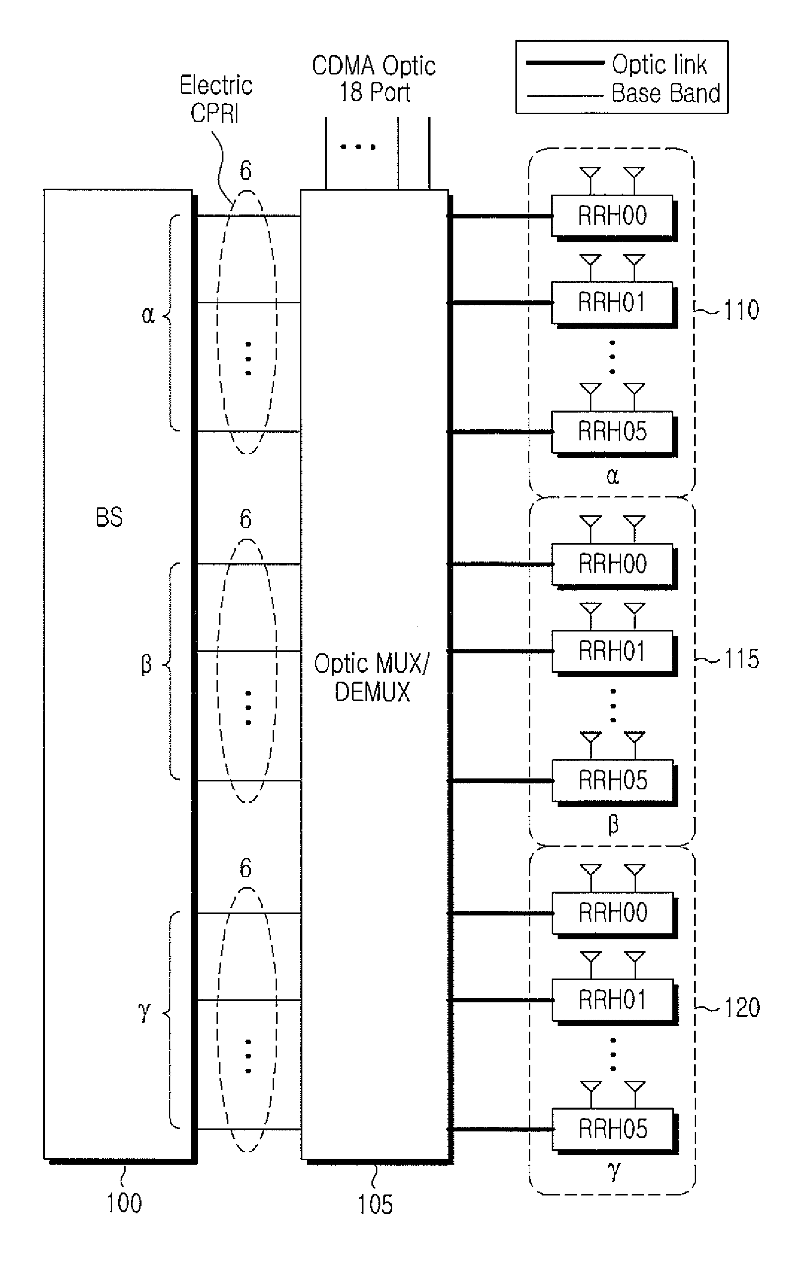
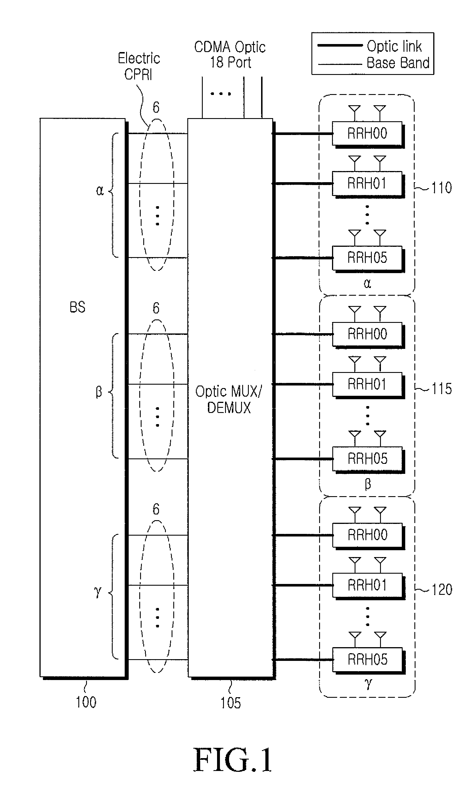
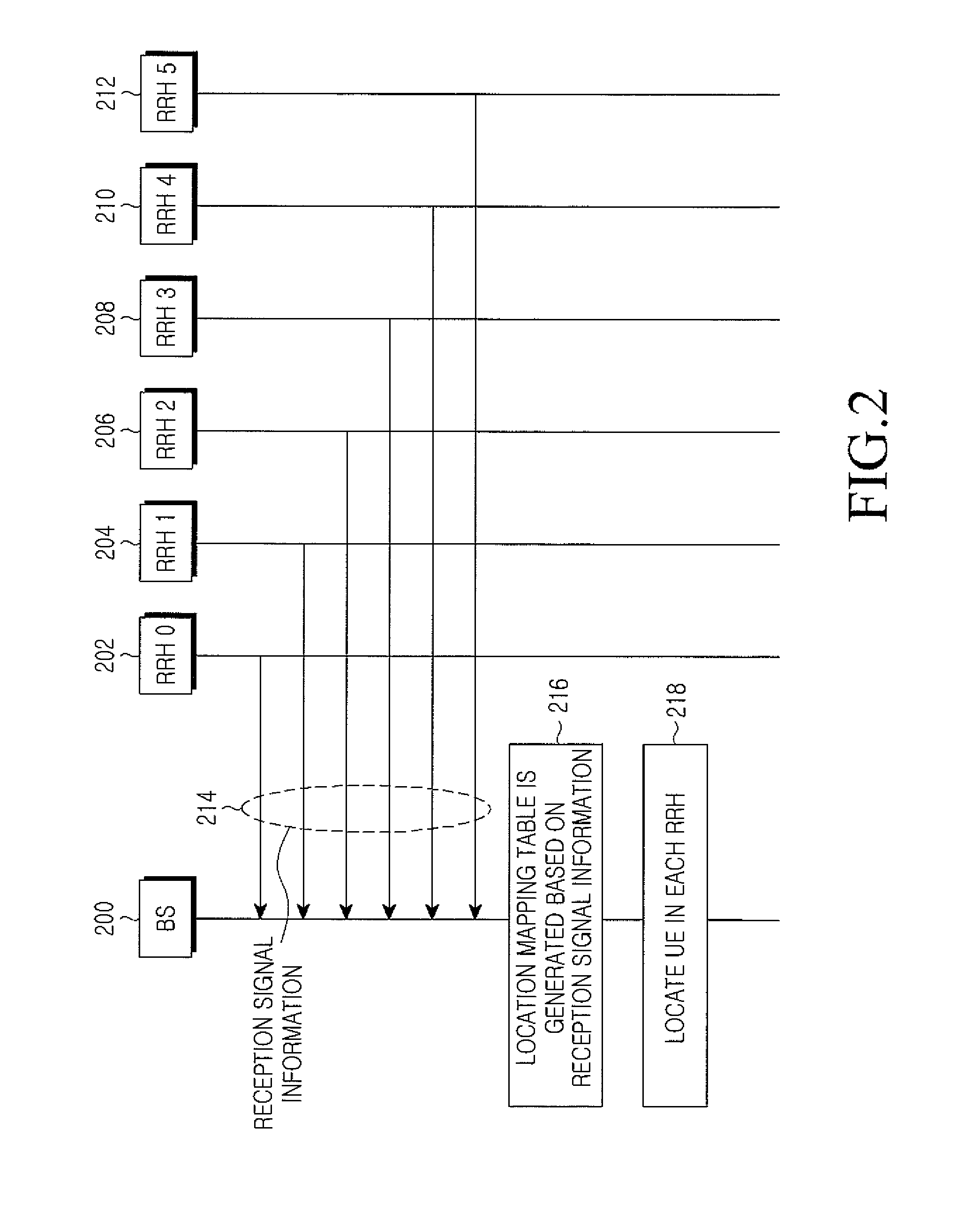
[0059]FIG. 3 is a diagram illustrating a signal flow for determining the location of a UE according to the present invention. It is assumed herein that a BS 300 is connected to six RRHs 302, 304, 306, 308, 310 and 312 (RRH 0 to RRH 5).

[0060]Referring to FIG. 3, the BS 300 receives SRS reception information from each of RRH 0 to RRH 5 in step 314. The SRS reception information specifies the strengths of SRSs received at the RRH, the IDs of UEs that transmitted the SRSs, and the RRH number of the RRH that received the SRSs.

[0061]In step 316, the BS 300 creates a location mapping table based on the SRS reception information received from RRH 0 to RRH 5. The BS then detects UEs having UE IDs mapped to the reception strength ‘strong’ of SRSs in the SRS reception information received from RRH 0 to RRH 5 and determines the UEs to be located in the partial service areas of RRH 0 to RRH 5 in step 318.

[0062]Apart from PRACH signals and SRSs received from UEs at the RRHs connected to the BS, t...


PUM


Abstract

A method and apparatus for determining a location of a User Equipment (UE) in a communication system. A Base Station (BS) connected to a plurality of antennas by cable receives from each of the antennas reception signal information related to an uplink signal transmitted from the UE, identifies an antenna having a partial service area in which the UE is located, using the reception signal information, and determines the partial service area of the identified antenna to be the location of the UE.

Description

CROSS-REFERENCE TO RELATED APPLICATION(S) AND CLAIM OF PRIORITY[0001]The present application is related to and claims the benefit of priority under 35 U.S.C. §119(a) to a Korean Patent Application filed in the Korean Intellectual Property Office on Jan. 29, 2010 and assigned Serial No. 10-2010-0008786, the contents of which are incorporated herein by reference.TECHNICAL FIELD OF THE INVENTION[0002]The present invention relates to a method and apparatus for determining the location of a User Equipment (UE) using an uplink signal received from the UE in a communication system.BACKGROUND OF THE INVENTION[0003]A communication system generally determines the location of a UE based on the location of a Base Station (BS). The following schemes are used to locate a UE.[0004]According to a location determination scheme in a network supporting a Global Navigation Satellite System (GNSS) (herein, referred to as a ‘GNSS’ scheme), both a BS and a UE are equipped with Global Positioning System (G...

Claims


Application Information

Patent Timeline
IPC IPC(8): H04W24/00
CPCH04W24/00H04W64/00H04B17/27H04W64/003H04W4/02G01S5/0252G01S5/0221G01S5/0226G01S11/06
Inventor CHEON, JUNG-HOONKIM, DAE-JOONGCHOI, SUN-YOUNGLEE, JU-MI
Owner SAMSUNG ELECTRONICS CO LTD
Features
  • Generate Ideas
  • Intellectual Property
  • Life Sciences
  • Materials
  • Tech Scout
  • Unparalleled Data Quality
  • Higher Quality Content
  • 60% Fewer Hallucinations
Learn More