Headrest for dental treatment chair and treatment chair

a technology for dental treatment and treatment chairs, which is applied in the field of headrests for dental treatment chairs and to dental treatment chairs, can solve problems such as pain in patients, and achieve the effects of reducing noise, reducing discomfort and reducing noise during dental treatmen

Active Publication Date: 2011-08-11
YAMADA TOMOMI
View PDF8 Cites 10 Cited by
  • Summary
  • Abstract
  • Description
  • Claims
  • Application Information

AI Technical Summary

Benefits of technology

[0024]According to the above configurations, a sound for reducing noise in the surrounding environment, such as music or a sound having the opposite phase of noise present in the surrounding environment, can be outputted, whereby discomfort due to noise during dental treatment can be reduced. In addition, the sound collecting section for collecting sounds in the surrounding environment is attached to the ear supporting members so as to be extendable from the ear supporting members. By extending the sound collecting section to the mouth of the dentist, minimum communication between the patient and the dentist can be ensured, whereby the patient can have treatment at ease.

Problems solved by technology

However, noise generated from dental treatment instruments such as an air turbine or a scaler includes a frequency component having a significantly high sound pressure level (see Non-Patent Document 2), and its sound range is higher than 8000 Hz.
In addition, noise generated from the air turbine, the scaler, or the like can cause a painful feeling to a patient.

Method used


Image

  • Headrest for dental treatment chair and treatment chair
  • Headrest for dental treatment chair and treatment chair
  • Headrest for dental treatment chair and treatment chair

Examples


Embodiment Construction

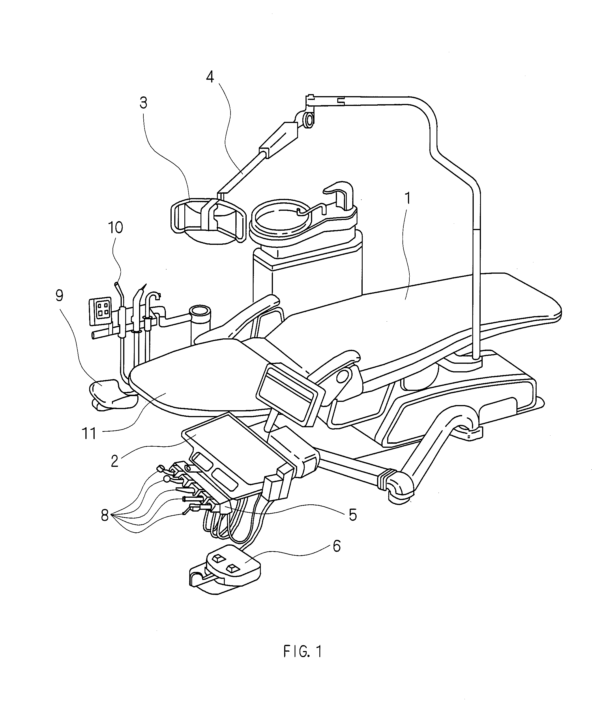
[0033]Hereinafter, a dental treatment chair according to an embodiment of the present invention will be described in detail with reference to the drawings. FIG. 1 is a perspective view showing the configuration of the dental treatment chair according to the embodiment of the present invention. The dental treatment chair according to the embodiment of the present invention has a backrest section 11 for supporting a back of a patient, a work table 2 which can be moved to a side of a face of the patient, an astral lamp 3 for illuminating a mouth, and an astral lamp arm 4 for moving the astral lamp 3 around a treatment chair 1 on which the patient sits.

[0034]The work table 2 is provided with an instrument holder 5 for accommodating various instruments 8, 8, . . . in dental treatment, e.g., an air turbine handpiece, an engine, and a three-way syringe. The operation of each of the instruments 8 except for the three-way syringe is controlled by a foot switch 6. In addition, a dental vacuum...


PUM


Abstract

The invention provides a headrest for a dental treatment chair and a dental treatment chair wherein discomfort due to noise generated from dental treatment instruments can be reduced and communication between a dentist and a patient can be ensured.
The headrest for the dental treatment chair and the dental treatment chair comprise a back head supporting member 91 for supporting a back of the head of the patient during dental treatment and ear supporting members 92 and 92 which can be bent in directions to cover ears of the patient at both ends of the back head supporting member 91. The ear supporting members 92 and 92 or the back head supporting member 91 has sound output sections 93 and 93 each for outputting a sound from a sound source, and the ear supporting members 92 and 92 have a sound collecting section 94 for collecting sounds in a surrounding environment. Acoustic filters 95 and 95 cut off frequencies higher than 8 kHz from a sound signal collected by the sound collecting section 94.

Description

[0001]This application claims the benefit under 35 U.S.C. Section 371, of PCT International Application No. PCT / JP2009 / 002882, filed Jun. 24, 2009, which claimed priority to Japanese Application No. 2008-225984, filed Sep. 3, 2008 in the Japanese Patent Office, the disclosures of which are hereby incorporated by reference.TECHNICAL FIELD[0002]The present invention relates to a headrest for a dental treatment chair and to a dental treatment chair wherein discomfort due to noise generated from dental treatment instruments can be reduced and communication between a dentist and a patient can be ensured.BACKGROUND ART[0003]Noise level meters are measuring instruments for obtaining important measured values of Environmental Quality Standards for Noise (Environment Agency Notification No. 64 of Sep. 30, 1998), Noise Regulation Law (Law No. 98 of Jun. 10, 1968), and the like. The performance of commonly used noise level meters is prescribed by JIS C 1502, and the frequency range to be measu...

Claims


Application Information

Patent Timeline
Patent Type & Authority Applications(United States)
IPC IPC(8): A61G15/12A47C7/72
CPCA61G15/10H04R5/023A61G15/125
Inventor YAMADA, TOMOMI
Owner YAMADA TOMOMI
Why Eureka
Try Eureka