Antenna assembly

a technology for antennas and brackets, applied in the field of antenna assemblies, can solve the problems of awkward and bulky antenna brackets, antennas that cannot be raised or lowered to clearly receive signals, and cannot be easily attached to monitors, etc., to achieve convenient adjustment, improve signal reception, and facilitate the effect of attaching to a monitor

Inactive Publication Date: 2011-08-11
TRANS ELECTRIC
View PDF2 Cites 5 Cited by
  • Summary
  • Abstract
  • Description
  • Claims
  • Application Information

AI Technical Summary

Benefits of technology

[0007]The main objective of the invention is to provide an antenna assembly which is easily attached to a monitor and is conveniently positioned for adjustment and improved receipt of signals.

Problems solved by technology

However, a flat surface is always needed for the placement of the antenna bracket, so users have to find a flat surface to mount the antenna bracket and this is not convenient.
Moreover, the antenna bracket is awkward and bulky because the antenna bracket occupies a space on a flat surface, such as a desk and cannot be mounted on a monitor.
Besides, the antenna is not capable of being raised or lowered to clearly receive signals.

Method used


Image

  • Antenna assembly
  • Antenna assembly
  • Antenna assembly

Examples


Embodiment Construction

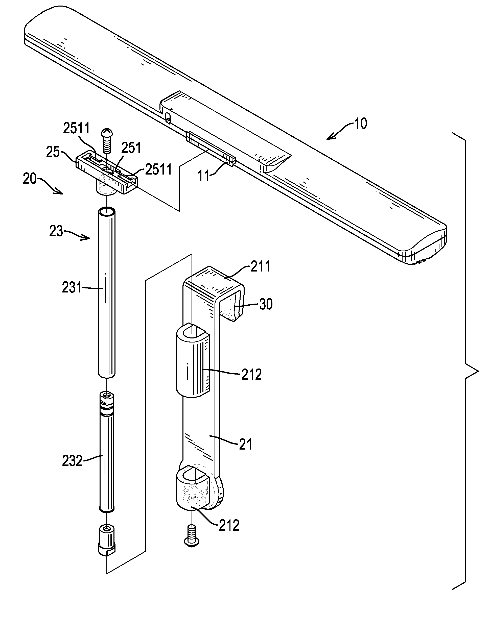
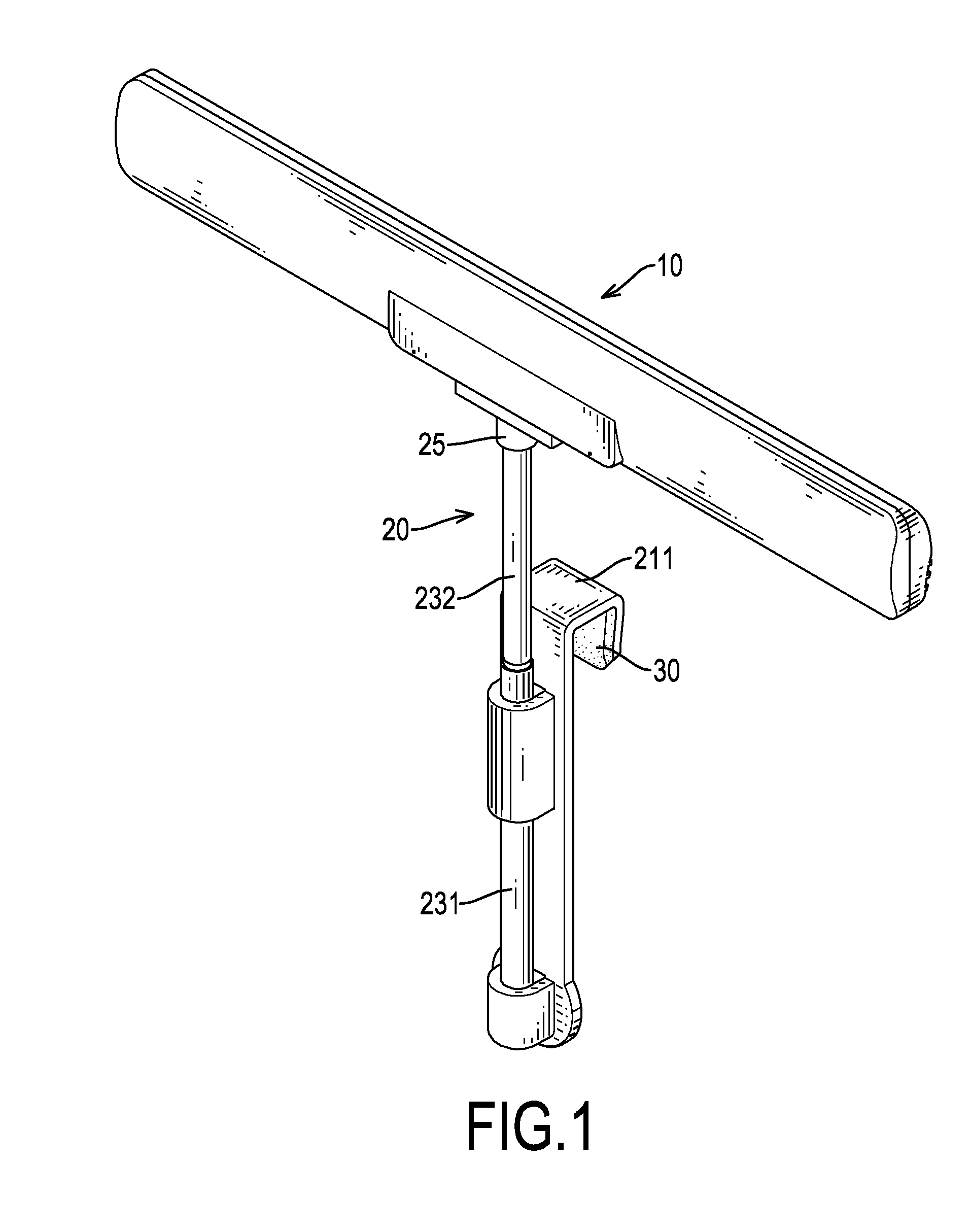
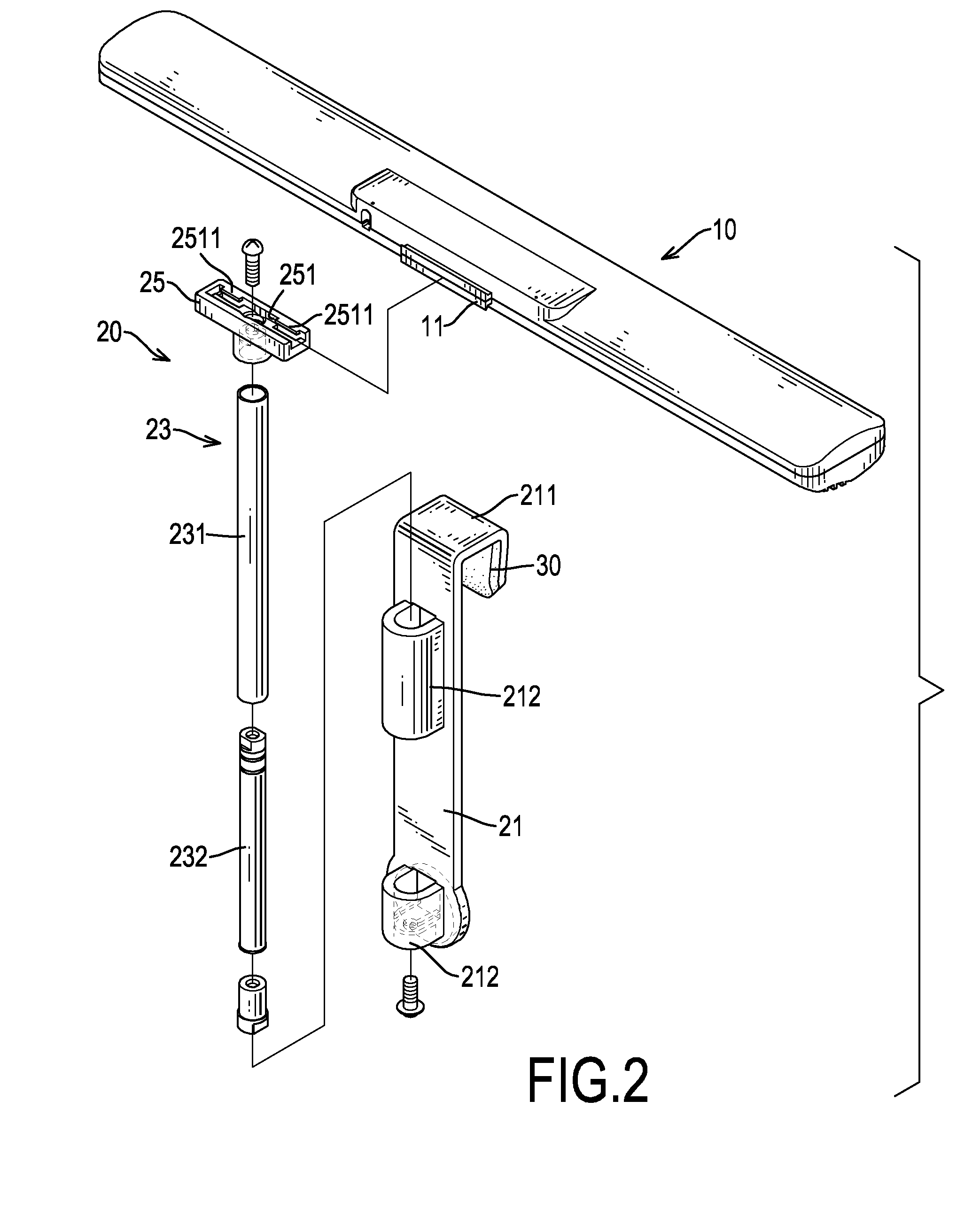
[0015]With reference to FIGS. 1 to 3, an antenna assembly in accordance with the present invention comprises an antenna (10), a bracket (20) and two pads (30).

[0016]The antenna (10) is horizontal and has a central segment and a rib (11). The rib (11) protrudes from the central segment of the antenna (10). Preferably, the rib (11) is dovetailed in cross section.

[0017]With further reference to FIG. 4, the bracket (20) is detachably connected with the antenna (10) and has a hanger (21), a telescopic strut (23) and an antenna stand (25).

[0018]The hanger (21) is elongated and has a top, a bottom, a hook (211), an outer side, an inner side and two base mounts (212). The hook (211) is formed on the top of the hanger (21) and has an inverted L-shaped cross section and an inner side. The inner side of the hook (211) faces the inner side of the hanger (21). The hook (211) can be attached to a monitor, maybe of a notebook as shown in FIG. 5. The outer side of the hanger (21) is opposite to the...


PUM


Abstract

An antenna assembly has an antenna and a bracket. The bracket is connected with the antenna and has a hanger, a telescopic strut and an antenna stand. The telescopic strut is mounted securely on the hanger and has a base tube and a moving rod mounted slidably and rotatably in the base tube. The antenna stand is mounted securely on the moving rod and is detachably connected with the antenna. Because the moving rod is capable of being raised, lowered and rotated relative to the hanger, it is very convenient and easy to position the antenna for adjustment and improved receipt of signals.

Description

BACKGROUND OF THE INVENTION[0001]1. Field of the Invention[0002]The present invention relates to an antenna assembly, and more particularly to an antenna assembly which is easily attached to a monitor and is conveniently positioned for adjustment and improved receipt of signals.[0003]2. Description of Related Art[0004]A conventional antenna assembly comprises an antenna and an antenna bracket. The antenna bracket has a bottom and a top on which the antenna is detachably mounted. The bottom of the antenna bracket is mounted on a flat surface, such as a desk.[0005]However, a flat surface is always needed for the placement of the antenna bracket, so users have to find a flat surface to mount the antenna bracket and this is not convenient. Moreover, the antenna bracket is awkward and bulky because the antenna bracket occupies a space on a flat surface, such as a desk and cannot be mounted on a monitor. Besides, the antenna is not capable of being raised or lowered to clearly receive sig...

Claims


Application Information

Patent Timeline
Patent Type & Authority Applications(United States)
IPC IPC(8): H01Q1/10F16M11/04H01Q3/02H01Q1/12
CPCH01Q1/10H01Q3/02H01Q1/2258H01Q1/12
Inventor WANG, CHENG-SI
Owner TRANS ELECTRIC
Why Eureka
Try Eureka