
Methods For Subsurface Parameter Estimation In Full Wavefield Inversion And Reverse-Time Migration

a full wavefield inversion and subsurface parameter technology, applied in the field of geophysical prospecting, can solve the problems of prohibitively large storage space for a realistic, suboptimal inversion, and the convergence of the inversion process is often very slow, and achieve the effect of reducing the cost of computational resources and reducing the cost of computation

Active Publication Date: 2011-08-11
EXXONMOBIL UPSTREAM RES CO
View PDF99 Cites 61 Cited by
  • Summary
  • Abstract
  • Description
  • Claims
  • Application Information

AI Technical Summary

Benefits of technology

The invention is a method for creating a model of a physical property in a subsurface region using seismic data. This method involves determining a seismic resolution volume and using it as a multiplicative scale factor in computations performed on a computer. The method can be used to either convert a gradient of data misfit or compensate reverse-time migrated seismic images to obtain the model of the physical property. The resulting model will have correct units and can be used for various practical applications.

Problems solved by technology

While Eqs. 8 and 9 provide the framework for inverting data into subsurface models, the convergence of the inversion process often is very slow.
Computation of the Hessian, however, is not only prohibitively expensive in computational resources, but it requires prohibitively large storage space for a realistic 3-D inversion problem.
Furthermore, FWI using the full Hessian matrix may result in suboptimal inversion [2].
These, however, still require computation of the full Hessian matrix or at least a few off-diagonal terms of the Hessian matrix, which can be costly computations.
This approach, however, does not provide quantitative inversion of the subsurface medium parameters with correct units, since only approximate scaling has been applied.
Furthermore, this approach was applied to RTM where only variations in compressional wave velocity is considered, and so may not be applicable to FWI where other elastic parameters such as density and shear wave velocity vary in space.

Method used


Image

  • Methods For Subsurface Parameter Estimation In Full Wavefield Inversion And Reverse-Time Migration
  • Methods For Subsurface Parameter Estimation In Full Wavefield Inversion And Reverse-Time Migration
  • Methods For Subsurface Parameter Estimation In Full Wavefield Inversion And Reverse-Time Migration

Examples


examples

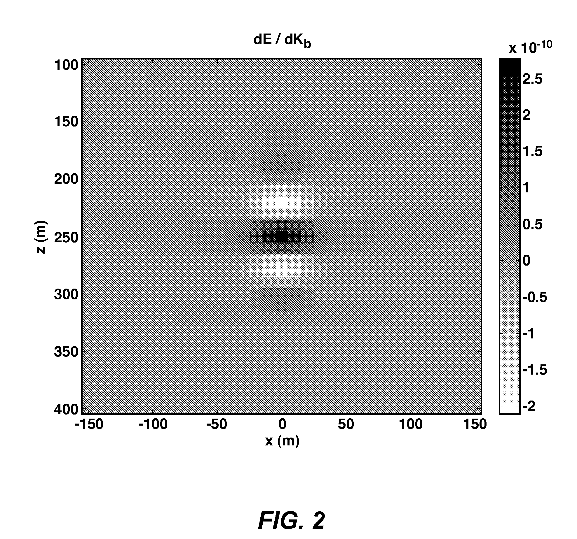
[0038]We consider the case of a 30 m×30 m×30 m “perfect” Born scatterer in a homogeneous medium with Kb=9 MPa and ρb=1000 kg / m3. The target is centered at (x,y,z)=(0,0,250 m), where x and y are the two horizontal coordinates and z is the depth. The target may be seen in FIGS. 2-7 as a 3×3 array of small squares located in the center of each diagram. We assume co-located sources and receivers in the −500 m≦x≦500 m and −500 m≦y≦500 m interval with the 10-m spacing in both x and y directions. We assume that the source wavelet has a uniform amplitude of 1 Pa / Hz at 1 m in the 1 to 51 Hz frequency band.

[0039]In the first example, we assume that the target has the bulk modulus perturbation given as Kd=900 kPa. FIG. 2 shows the gradient ∂E / ∂Kb(r) along the y=0 plane using Eq. 8. The scattered field pd in Eq. 8 has been computed using Eq. 5. The gradient in FIG. 2 has units of Pa m4 s, and so cannot be directly related to Kd. As described in the “Background” section above, this is a difficul...


PUM


Abstract

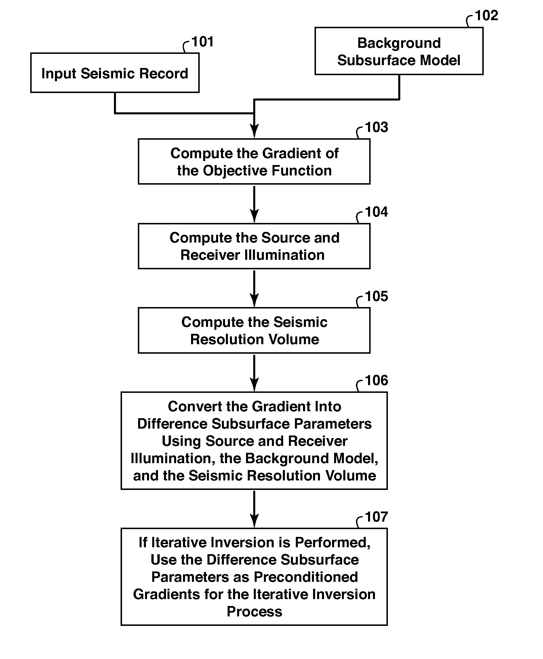
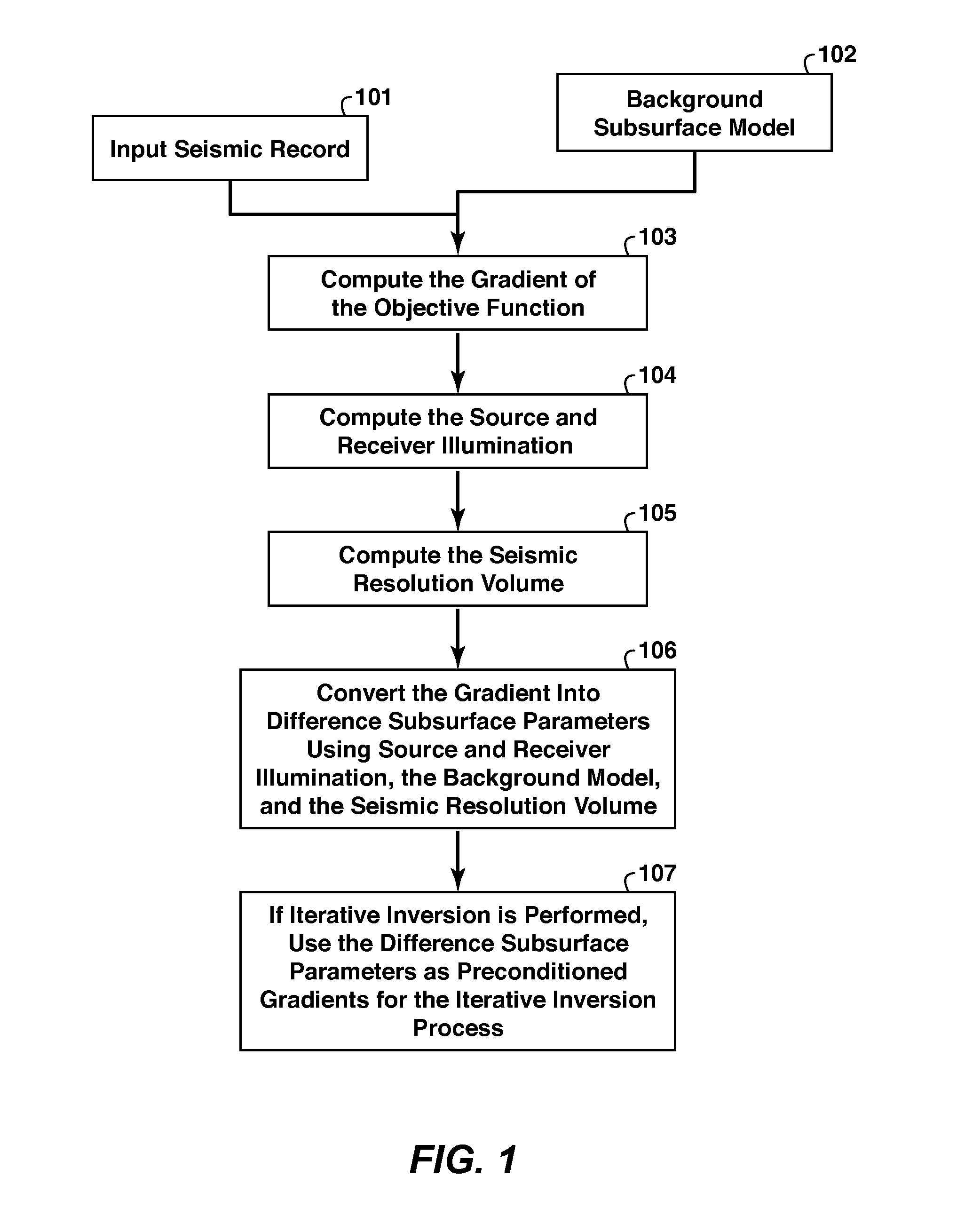
Method for converting seismic data to obtain a subsurface model of, for example, bulk modulus or density. The gradient of an objective function is computed (103) using the seismic data (101) and a background subsurface medium model (102). The source and receiver illuminations are computed in the background model (104). The seismic resolution volume is computed using the velocities of the background model (105). The gradient is converted into the difference subsurface model parameters (106) using the source and receiver illumination, seismic resolution volume, and the background subsurface model. These same factors may be used to compensate seismic data migrated by reverse time migration, which can then be related to a subsurface bulk modulus model. For iterative inversion, the difference subsurface model parameters (106) are used as preconditioned gradients (107).

Description

CROSS-REFERENCE TO RELATED APPLICATION[0001]This application claims the benefit of U.S. Provisional Application No. 61 / 303,148 filed Feb. 10, 2010, entitled Methods for Subsurface Parameter Estimation in Full Wavefield Inversion and Reverse-Time Migration, which is incorporated by reference, in its entirety, for all purposes.FIELD OF THE INVENTION[0002]This invention relates generally to the field of geophysical prospecting and, more particularly, to seismic data processing. Specifically, the invention is a method for subsurface parameter estimation in full wave field inversion and reverse-time migration.BACKGROUND OF THE INVENTION[0003]Full wavefield inversion (FWI) in exploration seismic processing relies on the calculation of the gradient of an objective function with respect to the subsurface model parameters [12]. An objective function E is usually given as an L2 norm asE=12∫∫∫p(rg,rs;t)-pb(rg,rs;t)2tSgSs,(1)where p and pb are the measured pressure, i.e. seismic amplitude, and ...

Claims


Application Information

Patent Timeline
Patent Type & Authority Applications(United States)
IPC IPC(8): G01V1/28
CPCG01V1/368G01V1/00G01V2210/679G01V1/282G01V2210/663G01V1/28G01V1/301G01V1/306G01V2210/51G01V2210/675G01V2210/614G01V2210/622
Inventor LEE, SUNWOONGKREBS, JEROME R.ANDERSON, JOHN E.BAUMSTEIN, ANATOLYHINKLEY, DAVID L.
Owner EXXONMOBIL UPSTREAM RES CO
Learn More