Full waveform joint inversion method for improving high steep structure velocity inversion efficiency

A technology of full waveform inversion and velocity inversion, which is applied in the field of petroleum geophysical exploration and can solve the problem of large amount of calculation of full waveform inversion.

Active Publication Date: 2016-06-15
CHINA UNIV OF PETROLEUM (EAST CHINA)
View PDF5 Cites 18 Cited by
  • Summary
  • Abstract
  • Description
  • Claims
  • Application Information

AI Technical Summary

Problems solved by technology

The calculation of full waveform inversion is very large, and the problem of calculation efficiency has become one of the research focuses of full waveform inversion

Method used


Image

  • Full waveform joint inversion method for improving high steep structure velocity inversion efficiency
  • Full waveform joint inversion method for improving high steep structure velocity inversion efficiency
  • Full waveform joint inversion method for improving high steep structure velocity inversion efficiency

Examples


Embodiment Construction

[0080] Below in conjunction with accompanying drawing and specific embodiment the present invention is described in further detail:

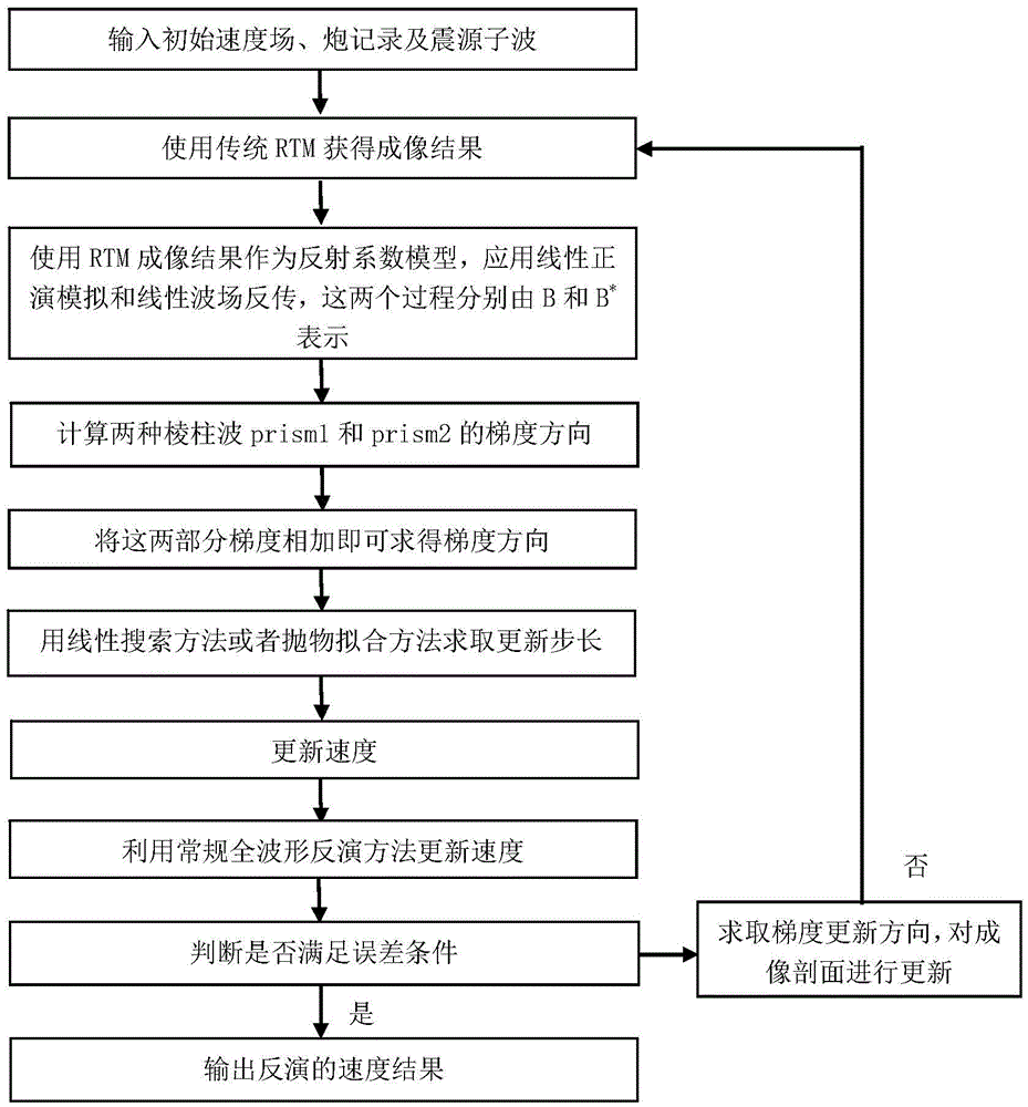
[0081] Flowchart of a full-waveform joint inversion method using prism wave information to improve the efficiency of velocity inversion for high and steep structures (such as figure 1 shown), including the following steps:

[0082] Input initial velocity field, shot record and source wavelet, and establish observation system;

[0083] Use traditional reverse time migration to obtain imaging results, use reverse time migration imaging results as the reflection coefficient model, apply linear forward modeling and linear wave field backpropagation;

[0084] Calculate the gradient directions of the two prism waves prism1 and prism2, and add the gradients of these two parts to obtain the gradient direction of the prism waveform inversion. Use the linear search method or parabolic fitting method to obtain the update step size, and use the obtained G...


PUM


Abstract

The invention discloses a full waveform joint inversion method for improving high steep structure velocity inversion efficiency, and belongs to the petroleum geophysical exploration field. The method comprises the steps: establishing an observation system by inputting the initial velocity field, the shot record and the focus wavelet; utilizing traditional reverse time migration to obtain the imaging result which is taken as a reflection coefficient model, and applying linear forward modeling and linear wave field back propagation; calculating the gradient directions of two prism waveforms and adding the gradient directions together to calculate the inverse gradient direction of the prism waveform, using the linear search method or a parabolic fitting method to calculate the updated step, and using the calculated gradient direction and step to update the velocity; using the conventional full waveform inversion method to update the velocity again, and determining whether or not to satisfy the error condition; if not, using the updated velocity as the input velocity, and updating the velocity again; and if so, outputting the inversion result. The full waveform joint inversion method for improving high steep structure velocity inversion efficiency reduces the dependency about whether the high steep structure information is missing in the initial model, and improves the inversion accuracy and efficiency for the high steep structure.

Description

technical field [0001] The invention belongs to the field of petroleum geophysical exploration, and in particular relates to a full-waveform joint inversion method for improving the efficiency of high-steep structural velocity inversion. Background technique [0002] Conventional primary reflection wave exploration, limited by the observation system, has insufficient illumination for steep-dipping underground structures such as faults and salt dome flanks, and it is difficult to accurately image high and steep structures. The prism wave information generated by the high and steep structures can effectively increase the illumination of the high and steep structures and improve the imaging effect of the high and steep structures. Therefore, it is very necessary to make full use of prism wave information to improve the imaging capability of high and steep structures. [0003] Due to the high precision and high resolution of full waveform inversion, it becomes a powerful tool f...

Claims


Application Information

Patent Timeline
Patent Type & Authority Applications(China)
IPC IPC(8): G01V1/28G01V1/30
CPCG01V1/282G01V1/303G01V2210/6161G01V2210/66
Inventor 曲英铭李振春黄建平李金丽
Owner CHINA UNIV OF PETROLEUM (EAST CHINA)
Why Eureka
Try Eureka