Image processing using shared frame memory

a frame memory and image processing technology, applied in the field of image processing methods, can solve the problems of difficult to stop at a desired scene at a proper timing, difficult to reverse-reproduce a data sequence, and difficult to reproduce a recorded data series

Inactive Publication Date: 2007-07-17
GK BRIDGE 1
View PDF13 Cites 20 Cited by
  • Summary
  • Abstract
  • Description
  • Claims
  • Application Information

AI Technical Summary

Benefits of technology

[0032]In any case of the above described, the coding or the decoding, and a processing accompanied by these as the case may be, may be performed in a predetermined unit of group. Moreover, different combinations of the above-described arbitrary structural components and processing processes and so forth, as well as expressions, used in the present invention, transferred between a method, an apparatus, a system, a computer program, a recording medium and so forth are still effective as and encompassed by embodiments of the present invention.

Problems solved by technology

Thus, it is extremely difficult to reverse-reproduce a data sequence, for the purpose of a picture search, which is coded and recorded in a time-series manner according to the MPEG, namely, it is extremely difficult to reproduce a recorded data series by simply going back along the time axis in the case of reproduction in the reverse direction as in the usual video tape recorder.
For example, the number of the I picture allotted for each GOP is at most one among pictures constituting the GOP, and when the picture of per 15 to 30 frames is reverse reproduced, a smooth reverse-reproduced picture as in the usual video tape recorder is not obtained, so that it is difficult to stop at a desired scene at a proper timing.

Method used


Image

  • Image processing using shared frame memory
  • Image processing using shared frame memory
  • Image processing using shared frame memory

Examples


first embodiment

[0048]This first embodiment exemplifies a structure considered in a case where each block constituting the structure of an image processing apparatus is, for example, made to a single chip. The structure for this embodiment does not particularly take into consideration a correspondence thereof to the present invention, and merely presents examples to be compared and referred to the subsequent embodiments.

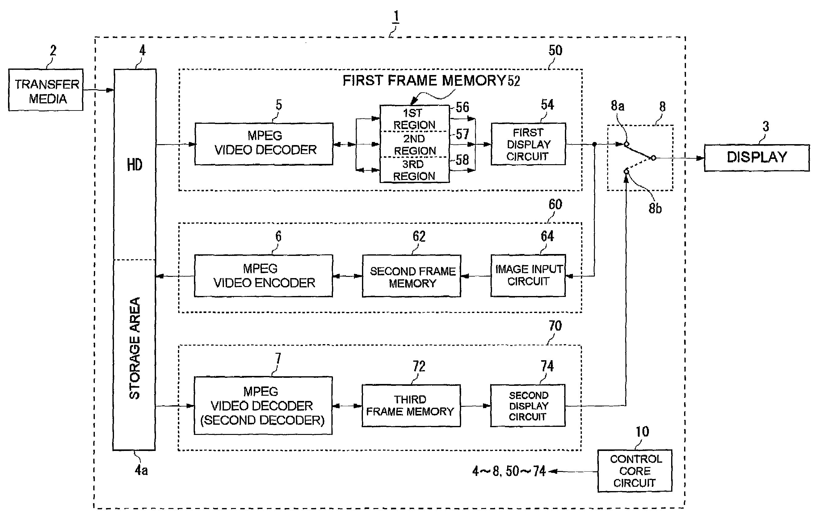
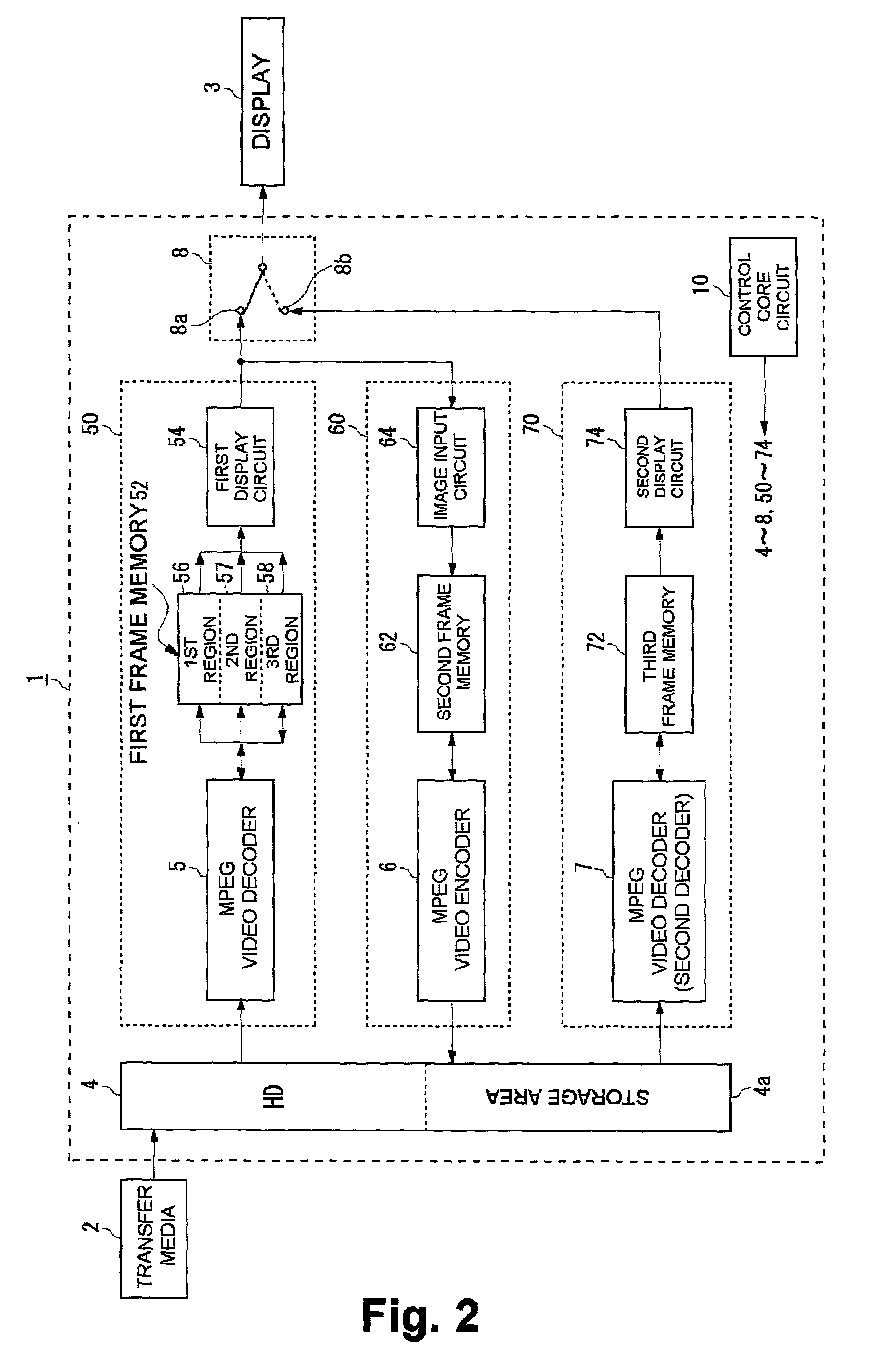
[0049]FIG. 2 shows a block circuit of an image reproducing apparatus 1 according to a first embodiment. This image reproducing apparatus 1 is incorporated into a movie camera, a still camera, a television, a video CD reproduction apparatus, a DVD reproduction apparatus or the like, which outputs the MPEG video stream from a transfer medium 2 to a display 3. The transfer medium 2 includes storage medium (video CD, CD-ROM, DVD, VTR and so forth), communication medium (LAN and so forth) and broadcasting medium (ground wave broadcasting, satellite broadcasting, CATV and so forth). Moreo...

second embodiment

[0071]This and subsequent embodiments have structures corresponding to the present invention. The second embodiment represents a more compact design version of the first embodiment. The second embodiment differs from the first embodiment in that the frame memories are so structured as to have a less capacity as a whole. That is, the first frame memory 52 and second frame memory 62 of the first embodiment are combined into one which is structured such that the total capacity thereof is for four frames.

[0072]FIG. 8 shows a block circuit of an image reproducing apparatus 1 according to a second embodiment. According to the first embodiment, the image video signals read out from the first display circuit 54 are recoded after they are converted to a reproduced image data sequence. In this second embodiment, however, a reproduced image data sequence before conversion into image video signals by the first display circuit 54 is read out and recoded. Hence, this second embodiment does not in...

third embodiment

[0080]A third embodiment represents a more compact design version of the second embodiment. The third embodiment differs from the second embodiment in that the frame memories are so structured as to have even less capacity as a whole. That is, the first frame memory 80 and second frame memory 90 of the second embodiment are combined into one which is structured such that the total capacity is for three frames only.

[0081]FIG. 9 shows a block circuit of an image reproducing apparatus 1 according to the third embodiment. A frame memory 100 is divided into a first region 102, a second region 104 and a third region 106, which correspond to the first region 82, the second region 84 and the third region 86 of the second embodiment, respectively. However, the third region 106 differs from the third region 86 of the second embodiment in that it is also used as a work area for a decoding processing by the second decoder 7. A display circuit 110 corresponds to the first display circuit 54 of t...


PUM


Abstract

When a reverse reproduction is instructed, an MPEG video stream is once decoded and is again recoded by an MPEG video encoder so as to generate a recoded data sequence which will be overwritten on a storage area in a hard disk. An MPEG video decoder reads out this recoded data sequence in a reverse time-series manner and decodes it successively, and then converts it to a video signal so as to be outputted to a display.

Description

BACKGROUND OF THE INVENTION[0001]1. Field of the Invention[0002]The present invention relates to an image processing method, and an image processing apparatus and a television receiver which can utilize the image processing method. The present invention relates to technology in which to process data coded according to, for example, the MPEG (Moving Picture Expert Group) standards.[0003]2. Description of the Related Art[0004]Information handled in the multimedia is of a vast amount and is multifarious, thus a fast processing of the information is necessary in the course of planning to put the multimedia to practical use. In order to process information at high speed, compression and expansion of data become indispensable. The “MPEG” method is one of data compression and expansion techniques. This MPEG method is being standardized by the MPEG Committee (ISO / IEC JTC1 / SC29 / WG11) under the ISO (International Organization for Standardization) / IEC (International Electro-technical Commissio...

Claims


Application Information

Patent Timeline
Patent Type & Authority Patents(United States)
IPC IPC(8): H04N5/91G06T9/00H04N7/26H04N7/50
CPCH04N19/40H04N19/423H04N19/127H04N19/61
Inventor OKADA, SHIGEYUKI
Owner GK BRIDGE 1
Why Eureka
Try Eureka