
Image forming apparatus and developing device used therein

a technology of image forming apparatus and developing device, which is applied in the direction of electrographic process apparatus, instruments, optics, etc., can solve the problems of damage or scratching of photoreceptors, and easy scattering of toner particles, so as to reduce the driving time of photoreceptors and prevent bending or breaking of cleaning blades

Inactive Publication Date: 2011-08-11
RICOH KK
View PDF24 Cites 15 Cited by
  • Summary
  • Abstract
  • Description
  • Claims
  • Application Information

AI Technical Summary

Benefits of technology

The present invention aims to provide an image forming apparatus and a developing device that can refill the developing device with an initial developer without damaging the photoreceptor or a cleaning blade and reducing unnecessary toner consumption as much as possible. The technical effects of the invention include reducing the photoreceptor driving time, preventing bending or breakage of the cleaning blade, and minimizing the discharge of excessive developer during the refill operation.

Problems solved by technology

In image forming apparatuses, developers are likely to scatter or fly off due to shaking or inclination during shipping or transportation of the apparatuses.
However, with this method, toner particles are easily scattered if the developing roller and the photoreceptor are positioned apart from each other.
However, because the shutter is an unwanted component for image reproduction, and because replacement of the developer is not carried out very often, it is desired to eliminate such a component to simplify the structure of the developing device.
The reason why the photoreceptor is driven at this timing is that the photoreceptor may be damaged or scratched unless it is operated during the activation of the developing device.
However, if the photoreceptor is driven without supplying toner particles to the cleaning part, the cleaning blade is likely to bend or break.
However, with this method, the photoreceptor is activated although the developer has not been supplied to the entire surface of the developing roller, and the toner belt cannot be formed at the full length along the longitudinal area of the photoreceptor.
In this case, the photoreceptor is driven under undesirable conditions with an insufficient amount of toner being supplied to the cleaning part.
In addition, since the time for driving the photoreceptor until the supplying of the initial developer is completed becomes long, the quantity of toner to be supplied to the cleaning part increases.

Method used


Image

  • Image forming apparatus and developing device used therein
  • Image forming apparatus and developing device used therein
  • Image forming apparatus and developing device used therein

Examples


first example

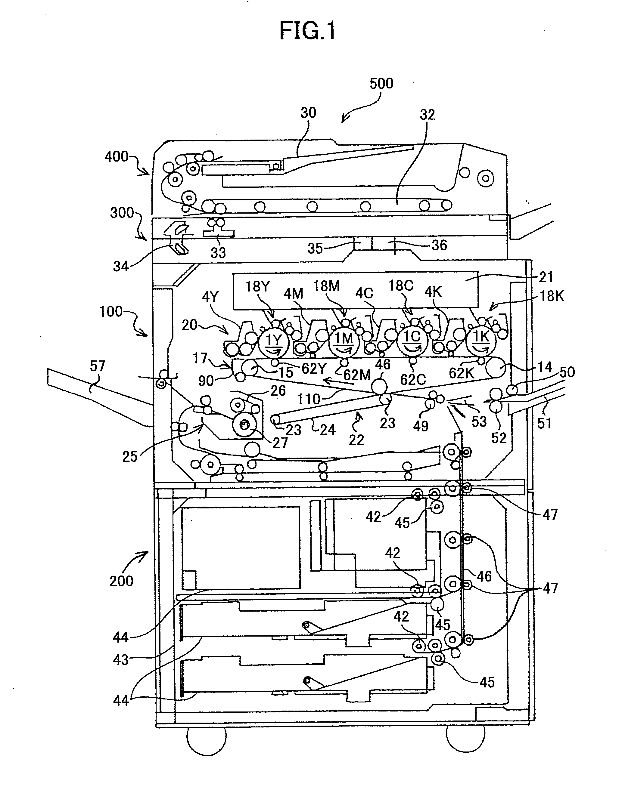
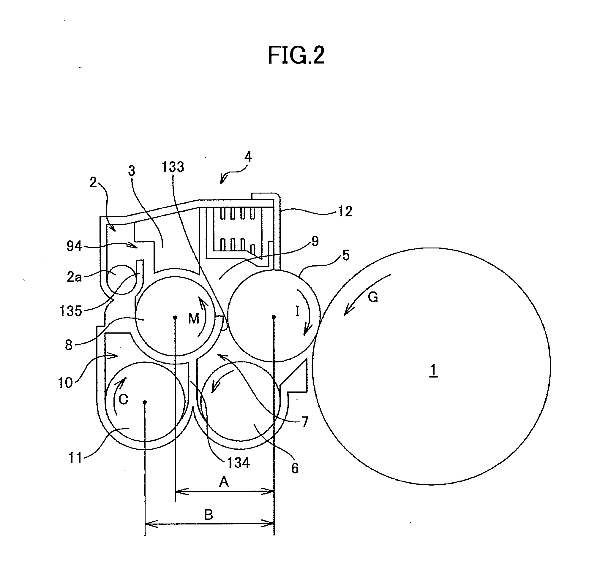
[0096]The image forming apparatus shown in FIG. 1 is furnished with a developing device which has the same structure as that shown in FIG. 4 except that the developer outlet port 94, the discharge feed path 2 and the discharge screw 2a are not provided. The developing device is refilled with initial developer manually from a gadget bag through the toner supply port 95.

[0097]FIG. 13 is a flowchart of the refill operation performed in the image forming apparatus of Example 1. Upon start of the refill operation and selection of the color (S101), the stirring feed screw 11 is driven to feed the initial developer supplied form the container to the developer feed path (S102). At the same time, the toner concentration sensor for detecting the permeability starts sensing. If the detected permeability is at or above a predetermined value (A) and if variation in the detected value has converged within a prescribed range (fluctuation range B) in a prescribed time, then it is determined that al...

example 2

[0099]The image forming apparatus shown in FIG. 1 is furnished with a developing device shown in FIG. 4 and initial developer is supplied from the bottle automatically upon setting the developer bottle 180 to the toner supply port 95 and unsealing of the bottle 180.

[0100]FIG. 14 is a flowchart of the refill operation performed in the image forming apparatus of Example 2. Upon start of the refill operation and selection of the color (S201), the stirring feed screw 11 is driven to feed the initial developer supplied from the developer bottle 180 to the developer feed path (S202). A time required for the developer to reach the bottom end of the developer outlet port 94 is measured as a setup time in advance. When setup time C (e.g., 8 seconds) has elapsed (YES in S203), the developing roller 5 is rotated (S204). A time required to supply the developer onto the entire surface of the developing roller 5 from the beginning of the rotation of the developing roller 5, under the condition of...

third example

[0106]According the process flow shown in FIG. 15, a refill operation is carried out in the same manner as in Reference Example. However, in Example 3, the driving operations for the stirring feed screw 11 and the discharge screw 2a are controlled independently, and the discharge screw 2a is not driven during the refill operation.

[0107]After the refill operation, a toner refill device (i.e., a refill unit) 600 is fixed to this image forming apparatus of Example 3, and initial developer is set up. Then a full solid image is printed. There was no adverse effect found in the printed image.

[0108]The reason for the clean image without causing unevenness in the density at the end of the printed image, unlike Reference Example, is that discharging of the developer through the developing outlet port 94 was restricted as much as possible. With this refill method, a time during which the photoreceptor 1 is stopped, while the developing roller 5 is driven, is shortened, and the photoreceptor 1...


PUM


Abstract

A developing device is refilled with an initial developer while the developing device and a photoreceptor are maintained within an image forming apparatus in the same state as in an image forming process. When refilling the developing device, a control unit of the image forming apparatus first drives a stirring feed member (screw) to feed the initial developer into the developing device, and then drives a developer carrier (developing roller) and a latent image carrier (photoreceptor) to supply the developer onto the developer carrier.

Description

TECHNICAL FIELD[0001]The present invention generally relates to an electrophotographic image forming apparatus such as a copy machine, a facsimile machine or a printer, and a developing device used therein. More particularly, the invention relates to a technique for supply an initial developer in an image forming apparatus while keeping the developing device and the photoreceptor inside the apparatus and for reducing toner consumption as much as possible without damaging the photoreceptor and the cleaning blade.BACKGROUND ART[0002]In image forming apparatuses, developers are likely to scatter or fly off due to shaking or inclination during shipping or transportation of the apparatuses. After an image forming apparatus is delivered to and installed in a certain place, a serviceman or the like has to refill the image forming apparatus with initial developer. Also, when replacing old developer with new developer, a service man may collect the old developer from the developing device an...

Claims


Application Information

Patent Timeline
Patent Type & Authority Applications(United States)
IPC IPC(8): G03G15/08
CPCG03G2215/0822G03G15/0822
Inventor MATSUMOTO, KEIKOYASUDA, MAKOTO
Owner RICOH KK
Learn More