This helps you quickly interpret patents by identifying the three key elements:
Problems solved by technology
Method used
Benefits of technology
Benefits of technology
[0014] An object of the present invention is to provide a washing machine that makes it possible to effectively exert a sterilizing effect onto all the inner wall face from the lower portion to the upper portion of the washing tank, to shorten the driving time required for washing the washing tank and also to reduce the amount of water to be used for the washing process.
[0016] With this structure, the water having a sterilizing effect, supplied into the washing tank, is allowed to move and flow along the entire inner wall face of the so-called taper-type washing tank by the centrifugal force derived from the rotation of the washing tank; therefore, even when a small amount of water is applied as the water having a sterilizing effect, it is allowed to easily reach the uppermost portion of the inner wall face of the washing tank by the centrifugal force. For this reason, soap dregs, microorganisms and the like adhering to the inner wall face of the washing tank can be washed away over the entire inner wall face of the washing tank, and sterilized so that it is possible to eliminate microorganisms such as fungi and bacteria that propagate over the inner wall face of the washing tank, and consequently to prevent contamination of the laundry by the microorganisms adhering to the inner wall face of the washing tank.
[0018] With this arrangement, since, after the rotation of the washing tank has been stabilized, water can be supplied into the washing tank, it is possible to prevent a rotation failure (unbalance) in the washing tank that tends to occur upon starting the rotation of the washing tank in which water has been preliminarily held.
[0022] With this arrangement, by using the silver ion having superior sterilizing effect and antifungal effect, the inner wall face of the washing tank can be sterilized so that bacteria even once propagated can be removed sufficiently.
[0024] Thus, it becomes possible to exert a sufficient sterilizing effect, in particular, to fungi that propagate on the inner wall face of the washing tank of a washing machine.
Problems solved by technology
With respect to the portions such as the bottom portion of the washing tank with which water and the laundry are made in contact during the washing process, in the case when the washing process is carried out usually, the propagation of microorganisms is limited since these portions are washed every time the washing process is carried out.
However, with respect to the upper portion of the washing tank, since such a washing effect is weak, microorganisms tend to vigorously propagate.
When the washing process is repeated under these circumstances, microorganisms are dispersed in the washing water to cause a problem that the laundry is stained.
Moreover, when microorganisms propagate in the washing tank, a problem of scattered microorganisms into the living environment might occur, and a visually unpleasant feeling tends to be given to the user.
Although there is the possibility that, for example, the wall face inside the inner tank, that is, portions near the water line and upper portions thereof, might be subject to propagation of bacteria and fungi, the tank washing processes, proposed in the above-mentioned patent publications, do not allow the chemical solution to make contact with the corresponding portions, thereby failing to properly provide the sterilizing and antibacterial effects.
For this reason, in order to wash the upper portion of the washing tank above the maximum water level, the stirring process needs to be carried out at the water level near the maximum water level, causing a large amount of water consumption.
Moreover, since a plurality of washing processes are carried out step by step, the driving time of the washing machine is prolonged, with the result that the corresponding increased power consumption is required.
Consequently, in the current trend of making products that impose little load onto the environment, this washing machine fails to take the environment issue into consideration.
Method used
Image
Click on the blue label to locate the original text in one second.
Reading with bidirectional positioning of images and text.
Examples
embodiment 1
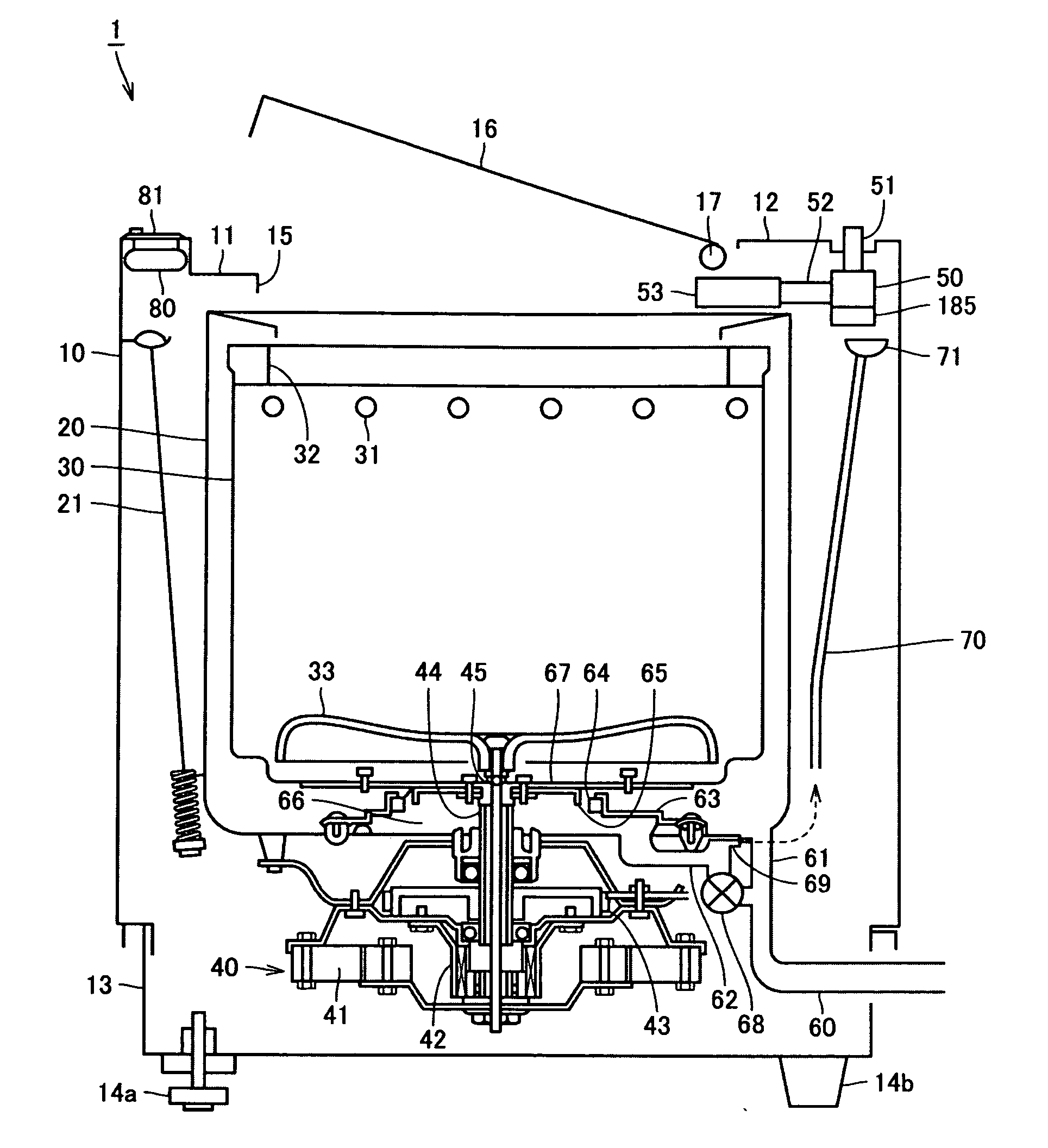
[0036] Referring to FIG. 1, the following description will discuss an embodiment of a washing machine as embodiment 1 of the present invention.
[0037] First, a structure of a washing machine of the present embodiment is explained. FIG. 1 is a longitudinal cross-sectional view showing the entire structure of a washing machine 1.
[0038] As shown in FIG. 1, supposing that a left side of the figure corresponds to a front face of the washing machine 1 and that a right side of the figure corresponds to a back face thereof, a back panel 12, made of synthetic resin, is installed in an overlapping manner on an upper face plate 11 made of synthetic resin in the same manner on the back face side of the washing machine 1. The back panel 12 is secured onto an outer case 10 or the upper face plate 11 with screws. A base 13 made of synthetic resin is superposed on a bottom face opening section of the outer case 10. The base 13 is secured onto the outer case 10 with screws. Here, in FIG. 1, the abo...
embodiment 2
[0087]FIG. 7 shows an example in which the control process in the “tank washing course” is different from that of the above-mentioned embodiment 1 as embodiment 2 of the present invention. In this embodiment, as shown in FIG. 7, after the washing tank 30 has started the tank rotation at a low speed, silver ion-containing water is supplied to the washing tank 30. The other processes are the same as those of embodiment 1.
[0088] By carrying out the tank washing course in accordance with the present embodiment, unbalance that tends to occur in the initial state of the tank rotation can be restrained. When water is held in the washing tank upon starting the tank rotation, load unbalance tends to occur in the entire washing tank due to the weight of the water, resulting in a failure in the driving. This is referred to as “unbalance”. However, in the case when, after the tank rotation has been started prior to the supply of water, the water is then supplied, the tank rotation can be maint...
embodiment 3
[0089]FIG. 8 shows another example in which the control process in the “tank washing course” is different from that of the above-mentioned embodiment 1 as embodiment 3 of the present invention. In this embodiment, as shown in FIG. 8, first, silver ion-containing water having a sterilizing function is supplied to the washing tank 30, and after the washing tank 30 has started the tank rotation at low speed, the silver ion-containing water is again supplied to the washing tank 30. The other processes are the same as those of embodiment 1.
[0090] In embodiment 1, although no unbalance occurred when 10 L of water was held in the washing tank, unbalance occurred when 15 L of water was held in the washing tank. In other words, depending on the amount of water held in the washing tank, the possibility of unbalance is raised. In embodiment 3, in the case when a certain amount of water is required due to the size of the washing tank, a comparatively small amount of silver ion-containing water...
PUM
Abstract
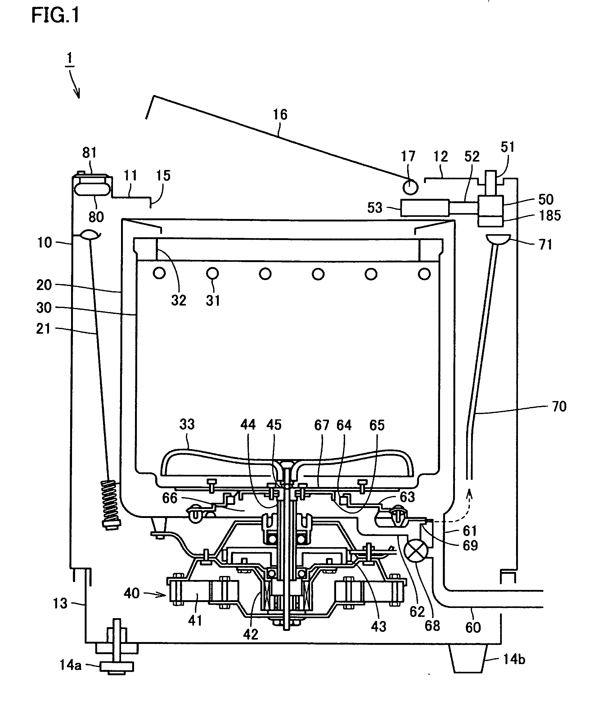
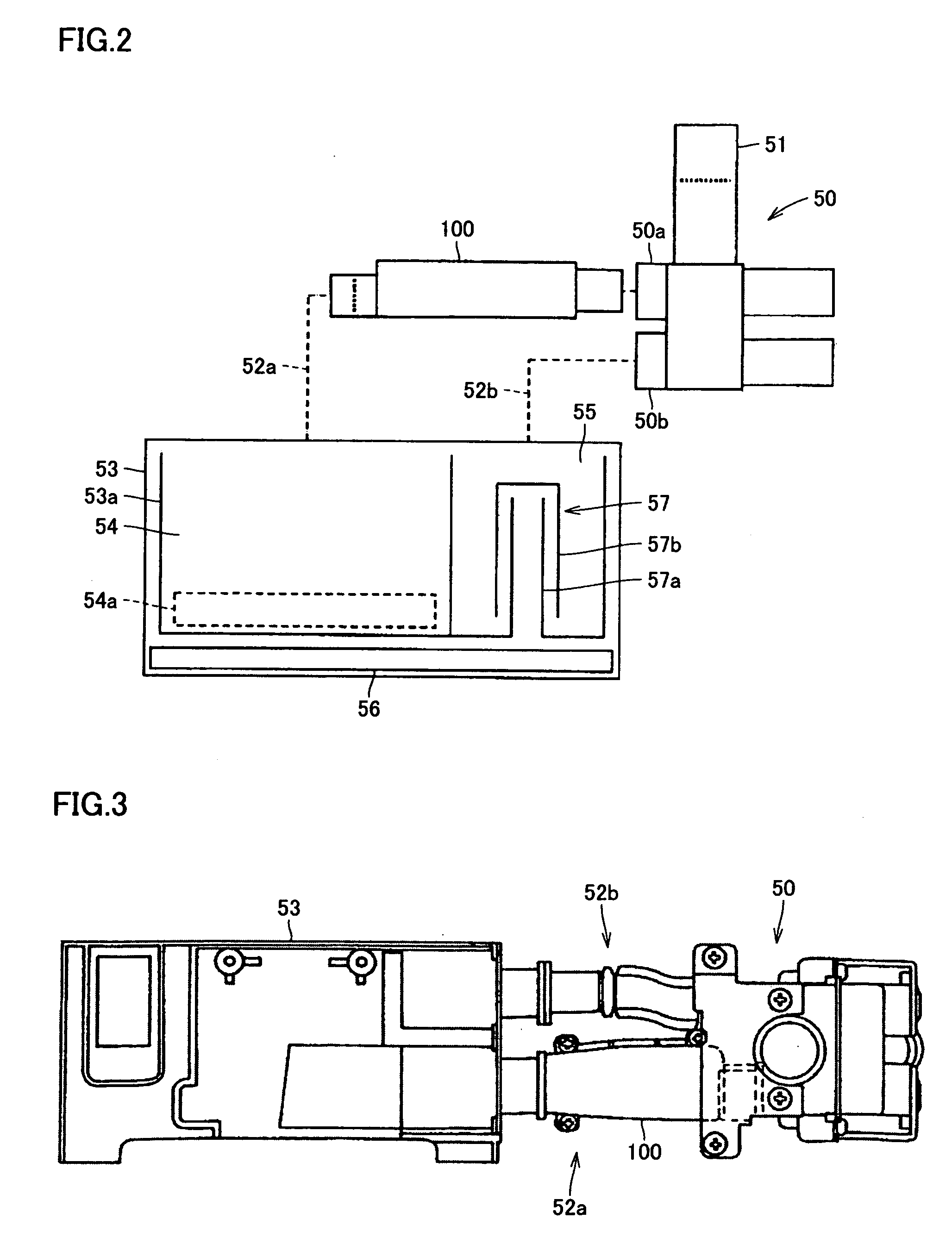
Provided is a washing machine that makes it possible to effectively exert a sterilizing effect onto all the inner wall face from a lower portion to an upper portion of a washing tank, to shorten a driving time required for washing the washing tank and also to reduce an amount of water to be used for the washing process. The washing machine is provided with a rotatable washing tank that has no hole in the tank wall, and is formed so that a diameter of the inner wall face becomes gradually greater toward an opening portion, as well as a water supply valve, a water supplypipe and an water supply inlet that serve as a water supply unit capable of supplying water having a sterilizing effect to the washing tank, and in this structure, silver ion-containing water, supplied to the washing tank by the water supply unit, is allowed to move and flow along the inner wall face of the washing tank by the centrifugal force derived from the rotation of the washing tank so as to sterilize the inner wall face of the washing tank.
Description
BACKGROUND OF THE INVENTION [0001] 1. Field of the Invention [0002] The present invention generally relates to a washing machine, and more particularly to a washing machine that has a function for removing microorganisms propagating on an inner wall face of a washing tank with which the laundry comes into contact. [0003] 2. Description of the Background Art [0004] When a washing machine carries out washing processes, soap dregs are deposited on an inner wall face of its washing tank. Microorganisms such as bacteria and fungi propagate with the soap dregs serving as a source of nutrition. The portions on which bacteria and fungi propagate basically include all the portions inside the washing tank. Microorganisms propagate not only on a bottom portion of the washing tank with which water is frequently made in contact usually, but also on, for example, portions along a water line on which stains are easily deposited as well as on an upper portion of the washing tank which is located ab...
Claims
Application Information
Patent Timeline
Application Date:The date an application was filed.
Publication Date:The date a patent or application was officially published.
First Publication Date:The earliest publication date of a patent with the same application number.
Issue Date:Publication date of the patent grant document.
PCT Entry Date:The Entry date of PCT National Phase.
Estimated Expiry Date:The statutory expiry date of a patent right according to the Patent Law, and it is the longest term of protection that the patent right can achieve without the termination of the patent right due to other reasons(Term extension factor has been taken into account ).
Invalid Date:Actual expiry date is based on effective date or publication date of legal transaction data of invalid patent.

