Method for producing a tubular compression item, and item thereby obtained

Active Publication Date: 2015-09-03
THUASNE SA
View PDF90 Cites 18 Cited by
  • Summary
  • Abstract
  • Description
  • Claims
  • Application Information

AI Technical Summary

Benefits of technology

[0026]Advantageously, a twin cylinder knitting machine gives the possibility of laying the weft thread between two rows of consecutive stitches without blocking it by having it pass through the feet of the stitches so that the weft thread is found between the knitted stitches on the location forming the outer face of the item and the knitted stitches on the back forming the inner face of the compression item. In the leg part and foot portions knitted with a mesh thread along ribbed stitches and an elastic weft thread, the weft thread thus forms a somewhat intermediate layer positioned between the outer

Problems solved by technology

The greater the deficiency of the venous system, the more blood has difficulties for reflowing from the ankle back towards the heart, and the higher is the pressure to be exerted at the ankle.
The compression items, notably of a high class, are difficult to slip on by the patient, notably when the latter suffers from reduced mobility.
The tuck stitch areas of the weft thread form areas blocking the weft thread in the transverse direction of the knitted tubular item limitin

Method used


Image

  • Method for producing a tubular compression item, and item thereby obtained
  • Method for producing a tubular compression item, and item thereby obtained
  • Method for producing a tubular compression item, and item thereby obtained

Examples


Embodiment Construction

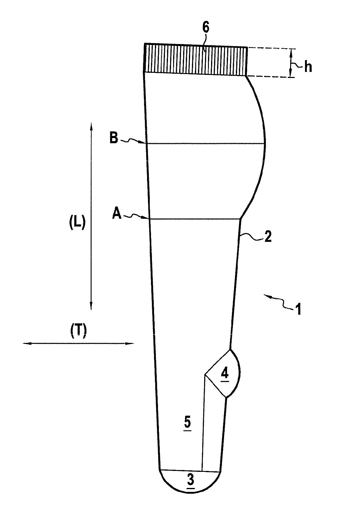
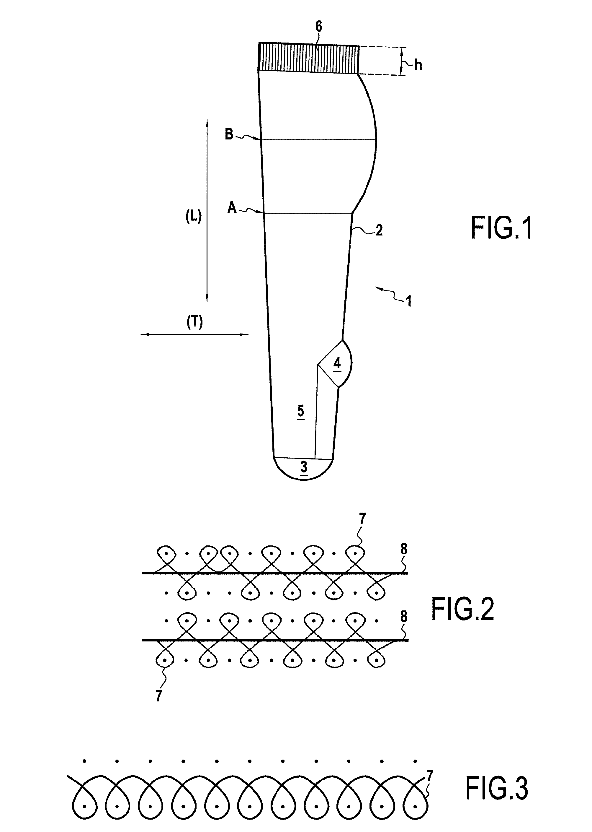
[0078]The tubular compression item 1 illustrated in FIG. 1 is a sock comprising a leg part 2, a foot tip 3, a heel 4, a foot 5 and a ribbed edge 6 in the extension of the leg part 2.

[0079]The whole of the item 1 is knitted on a twin cylinder knitting machine, i.e. comprising upper and lower superposed cylinders each working with a determined number of needles (m).

[0080]The tubular item 1 comprises a longitudinal direction (L) and a transverse direction (T) corresponding to the direction of the columns of stitches and to the direction of rows of stitches respectively.

[0081]The leg part 2, the foot 5 and the ribbed edge 6 comprise several rows of ribbed stitches respectively (n)*(p), (n′)*(p′) and (n″)*(p″) knitted with a mesh thread 7 illustrated in FIG. 2, between which are inserted elastic weft threads 8 every 1 / 1 to 1 / 5 rows of stitches. In this specific example, the elastic weft thread 8 is inserted every 1 / 1 to 1 / 2 rows of ribbed stitches (n)*(p) and (n′)*(p′), preferably betwee...


PUM

PropertyMeasurementUnit
Lengthaaaaaaaaaa
Fractionaaaaaaaaaa
Heightaaaaaaaaaa

Abstract

The object of the present invention is a method for manufacturing a tubular compression item (1), having at least one leg part (2), one foot tip (3), one heel (4) and one foot (5), comprising a first step for knitting the leg part (2) and the foot (5) with at least one mesh thread (7) on a twin cylinder knitting machine during which an elastic weft thread (8) is inserted between two rows of ribbed stitches (n)*(p) and (n′)*(p′) every 1/1 to 1/5 rows of stitches of the leg part (2) and of the foot (5), on at least 50% by number of the number (m) of needles without forming any tuck stitch or loop stitch.

Description

BACKGROUND OF THE INVENTION[0001]The present invention relates to the technical field of methods for manufacturing tubular compression items, in particular items exerting gradual compression from the ankle up to the top of the leg.[0002]Compression items, socks or knee-length stockings, stockings, pantyhoses or further sleeves, are used for preventing or caring for venous circulation problems notably at the lower or upper limb, as well as pathologies related to malfunctions of the lymphatic system and reduction of edemas. Venous disorders may have several origins, among which are notably found: rigidification of the vein wall, alteration of the valvulae or further an increase in the diameter of the veins.[0003]The local pressure exerted on a limb by an item with a compressive effect notably depends on the force-elongation characteristics of said item.[0004]The pressure exerted on a limb is calculated by the following Laplace law:P [Pa or mmHg]=(T [N]×n / (L [m]×R [m]).[0005]P represen...

Claims


Application Information

Patent Timeline
IPC IPC(8): A61F13/08D04B15/18D04B1/26
CPCA61F13/08D04B15/18D04B1/265A61F13/00004A61F13/00038D04B1/26D04B1/106D04B1/18
Inventor CONVERT, REYNALDRUER, AURELIACATTIAUX, GERARDMOTET, PASCAL
Owner THUASNE SA
Why Eureka
Try Eureka