

Fluidized-bed polymerization method and polymerization reactor
A technology of polymerization reactor and polymerization method, which is applied in the field of fluidized bed polymerization method and its polymerization reactor, can solve the problems of undisclosed literature and patent reports, and achieve the effects of expanding the scope, shortening the start-up time, and preventing the loss
- Summary
- Abstract
- Description
- Claims
- Application Information
AI Technical Summary
Problems solved by technology
Method used
Image

Examples
Embodiment 1
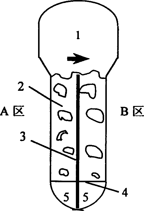
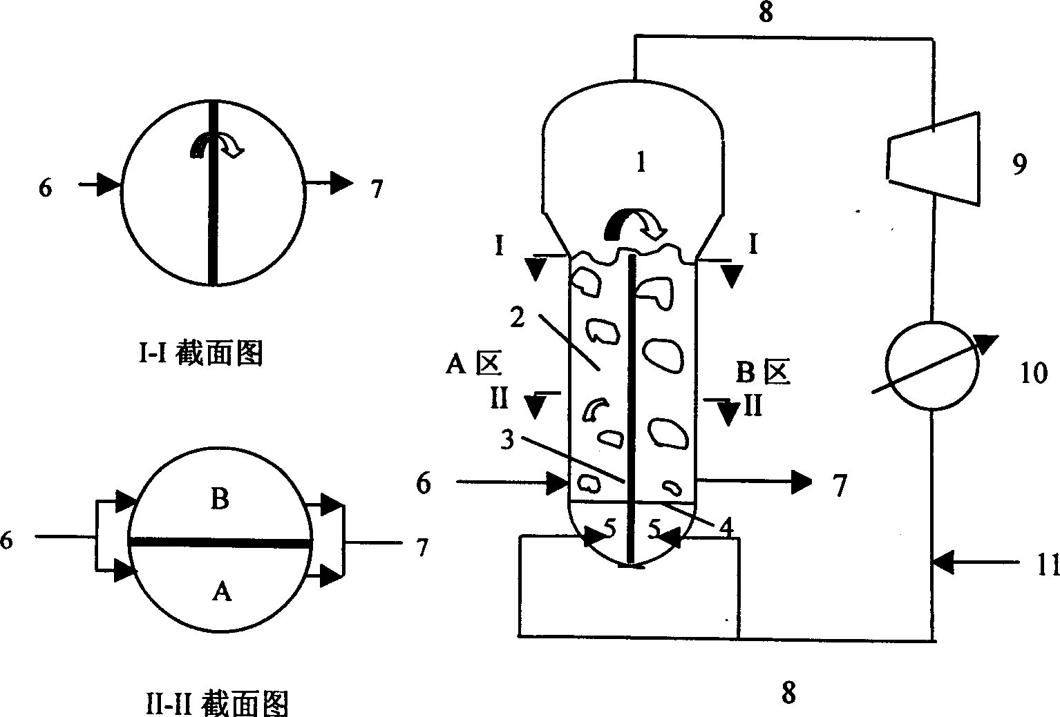
[0025] Such as figure 1 is a schematic diagram of the fluidized bed structure partition, figure 2 It is a schematic flow chart of the gas phase ethylene polymerization fluidized bed reactor process. The gas bed is divided into two areas, A and B. The cross-sectional area of A as the start-up bed accounts for 1 / 2 of the total bed area. The air intake of A and B areas are independently adjusted by their respective air intake control systems. Catalyst feed and polymer discharge system are also adjusted by the feed and discharge control system. Two feeds can be fed at the same time, or one of them can be closed to allow one feed ( figure 1 - I-I and II-II sectional views). Dichlorinated bis(1,3-methyl-n-butylcyclopentadienyl) zirconium metallocene dry powder is continuously sprayed into zone A of the fluidized bed after metering to carry out copolymerization of ethylene and butene, and the polymerization pressure is 2.05MPa , the polymerization temperature is 85°C, the supe...
Embodiment 2
[0030] Such as figure 2 It is a schematic flow chart of the gas phase ethylene polymerization fluidized bed reactor process. The bed is divided into two areas, A and B, and the cross-sectional area of A as the start-up bed only accounts for 1 / 2 of the total bed area. Under the system of bis(1,3-methyl-n-butylcyclopentadienyl) zirconium metallocene dichloride, the polymerization of ethylene and butene is carried out, the polymerization pressure is 2.05MPa, the polymerization temperature is 85°C, and the reactor is empty. The speed is 0.65m / sec, and the design capacity of the reactor is 90kgPE / m 3 ·hr. After metering, the dry catalyst powder is continuously sprayed into zone A of the fluidized bed for heterogeneous (co)polymerization of ethylene to produce linear low-density polyethylene resin. The polymer product is continuously discharged through the discharge device in zone B to keep the height of the fluidized bed constant. The circulating gas containing monomers, com...
Embodiment 3
[0035] Such as figure 2 It is a schematic flow chart of the gas phase ethylene polymerization fluidized bed reactor process. The bed is divided into two areas, A and B, and the cross-sectional area of A as the start-up bed only accounts for 1 / 3 of the total bed area. After being metered, the high-efficiency catalyst dry powder is continuously sprayed into the A zone of the fluidized bed for heterogeneous (co)polymerization of ethylene, and the produced linear low-density polyethylene resin is discharged from the reactor B.
[0036] When switching from grade 1 to grade 2, the operating conditions of grades 1 and 2 are shown in Table 1. When switching operation, cut off the internal channels of the particles in the A zone and B zone, through the polymer discharge port of the B zone, the polymer in the B zone is gradually discharged from the reaction zone, and at the same time, the polymer discharge valve in the A zone is opened to control the fluidization of the A zone The ...
PUM
 Abstract
Description
Claims
Application Information