Hydraulic apparatus with direct torque control

Inactive Publication Date: 2011-08-11
UT BATTELLE LLC
View PDF22 Cites 44 Cited by
  • Summary
  • Abstract
  • Description
  • Claims
  • Application Information

AI Technical Summary

Benefits of technology

[0008]A hydraulic apparatus with direct torque control includes a cam body, the cam body being rotatable about an axis and having at least two mirror image involute cam surfaces on opposing sides of the axis. At least two hydraulic actuators are provided on opposing sides of the axis. Each of the actuators has a linearly extendable ram and a hydraulic cylinder. The ram has a piston positioned in the hydraulic cylinder and each ram is extendable to contact the involute cam surface on the respective opposing side of the axis. A fluid supply line is provided for delivering a pressurized fluid to each of the cyl

Problems solved by technology

There is no direct way of directly controlling torque to a conventional hydraulic joint.
These devices can be heavy and can generate a significant amount of heat.
Hydraulic actuators have not frequently been us

Method used


Image

  • Hydraulic apparatus with direct torque control
  • Hydraulic apparatus with direct torque control
  • Hydraulic apparatus with direct torque control

Examples


Embodiment Construction

[0034]The subject of this invention is a hydraulic apparatus that enables direct control of torque. The invention provides direct torque control, using fluid power, of a compact mechanical apparatus such as a prosthetic joint. The joint can provide high torques with less volume and weight than electric motors, and remains very cool, which is important for wearable devices. This invention provides a direct means to provide torque proportional to an input electrical signal. This characteristic is critical for wearable force controlled devices. The joint is free to move when there is no electrical power. Therefore it is fail safe. Likewise, resistance torque increases with increasing electrical command.

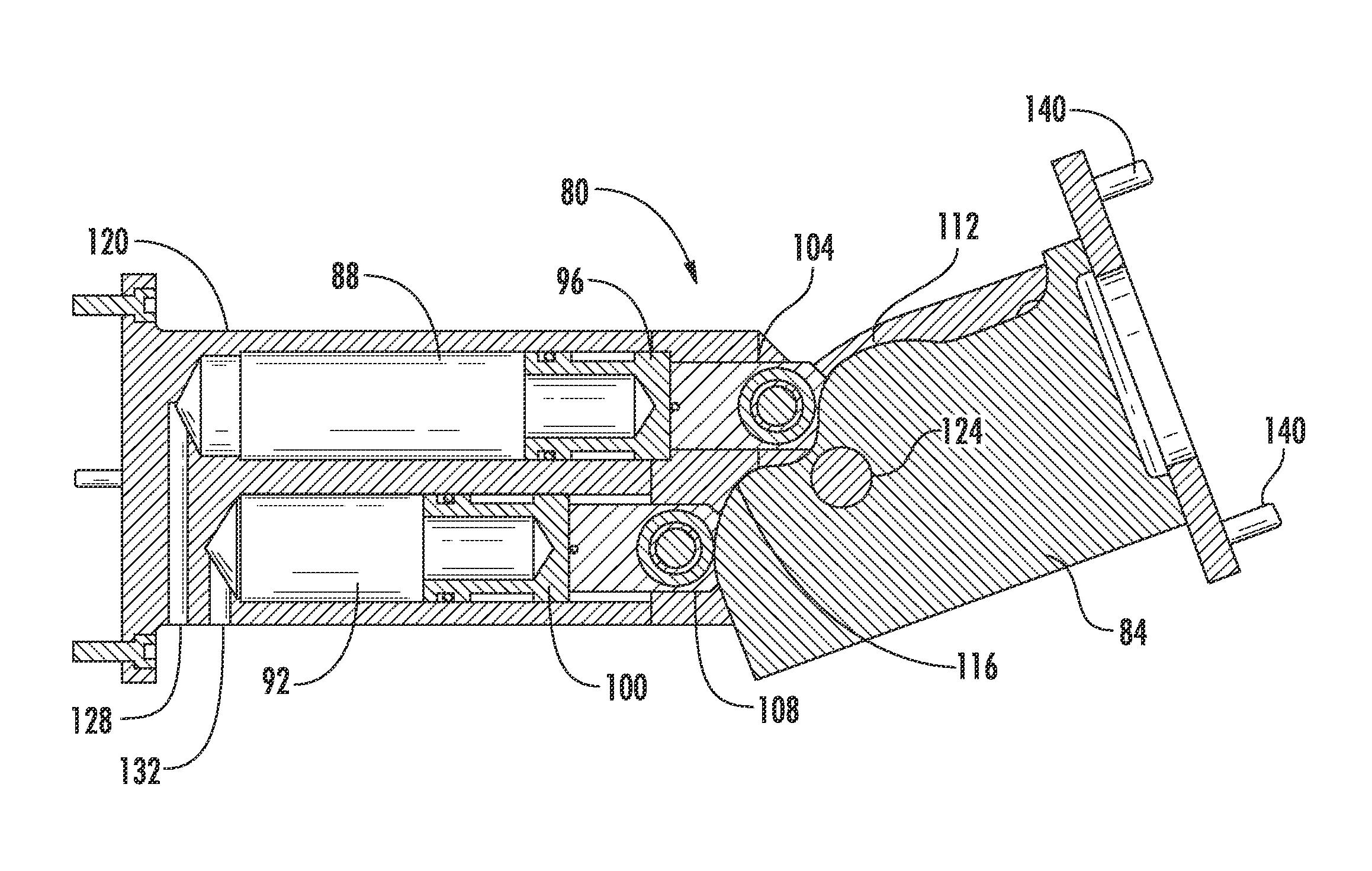
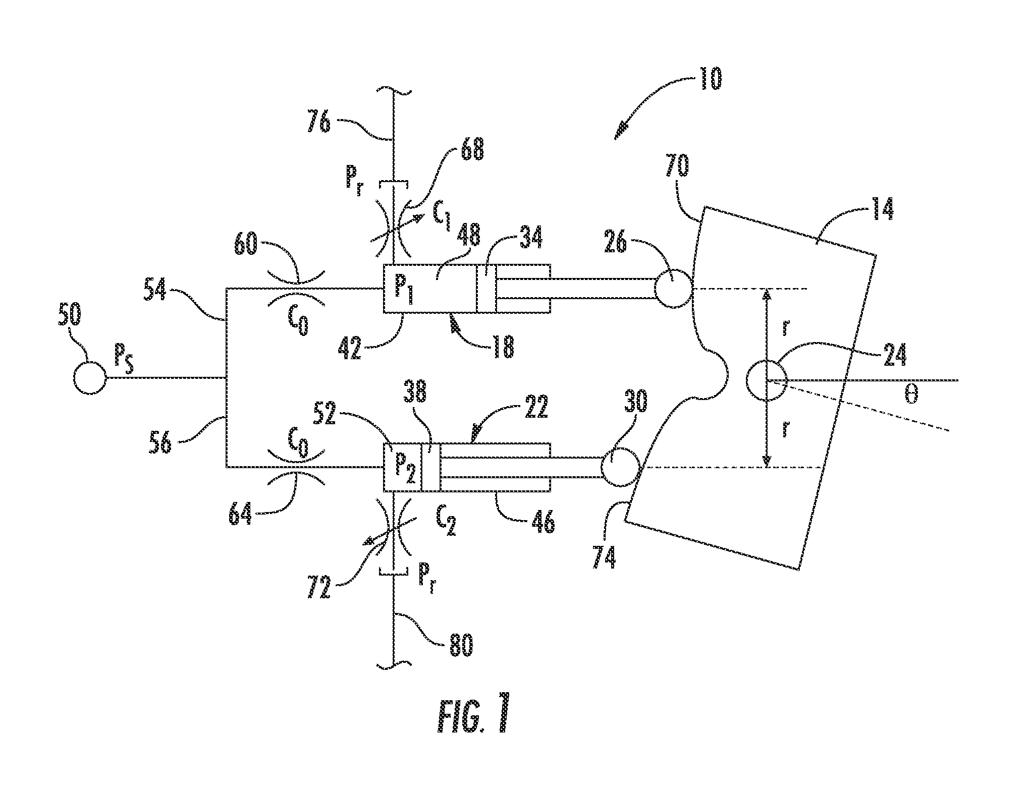
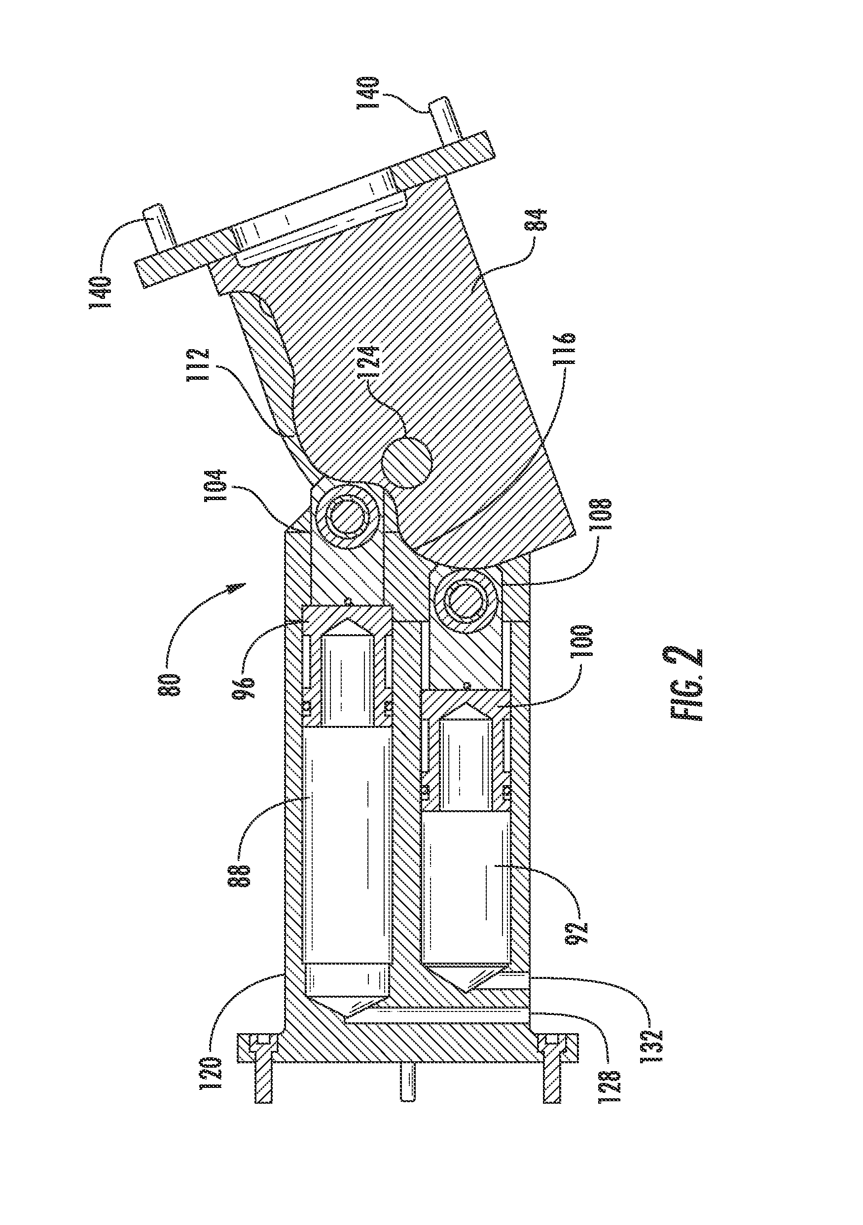
[0035]As shown in FIG. 1, the joint assembly 10 has an involute cam body 14 and a pair of actuators 18 and 22. The cam body 14 is rotatable about an axis 24. The actuators 18 and 22 have rams 26 and 30, which are connected to pistons 34, 38 positioned within cylinders 42 and 46 providing...


PUM


Abstract

A hydraulic apparatus has a cam body rotatable about an axis and with at least two mirror image involute cam surfaces on opposing sides of the axis. Hydraulic actuators on opposing sides of the axis have a linearly extendable ram and a hydraulic cylinder. A fluid supply line is provided for delivering a pressurized fluid equally to each of the cylinders. A pressure relief or flow control valve is associated with each of the hydraulic cylinders and is operable to selectively assume a closed position to retain fluid or assume an open position to release fluid from the hydraulic cylinders. A control can operate the pressure relief valves between at least the closed and open positions, to move the rams out of and in to the cylinders to rotate the cam body about the axis with controlled torque. A robotic, prosthetic or orthotic and a method for applying torque to a body are also disclosed.

Description

CROSS-REFERENCE TO RELATED APPLICATIONS[0001]This application is a continuation-in-part of U.S. patent application Ser. No. 12 / 394,276, filed Feb. 27, 2009, and also claims priority to International Application No. PCT / US2010 / 025199, filed Feb. 24, 2010, the entireties of which are incorporated by reference herein.STATEMENT REGARDING FEDERALLY SPONSORED RESEARCH OR DEVELOPMENT[0002]This invention was made with government support under DE-AC05-00OR22725 awarded by The United States Department of Energy. The government has certain rights in the invention.FIELD OF THE INVENTION[0003]This invention relates to actuators, and particularly to hydraulic actuators useful for haptic devices.BACKGROUND OF THE INVENTION[0004]Actuators convert energy (electrical, mechanical, chemical, thermal) to mechanical motion. Examples include solenoids, electric motors, hydraulic and pneumatic pistons, piezoelectrics, shape memory alloys and electroactive polymers. The predominant form of actuation in indu...

Claims


Application Information

Patent Timeline
IPC IPC(8): A61F2/74F15B13/06F15B15/20
CPCB25J9/109B25J9/144F15B15/061B25J17/0275B25J17/0241
Inventor JANSEN, JOHN F.LIND, RANDALL FRANKLOVE, LONNIE J.
Owner UT BATTELLE LLC
Why Eureka
Try Eureka