
Service level cross network coordinated interaction

a cross-network, interaction technology, applied in the direction of instruments, digital computers, computing, etc., can solve the problems of limiting the ability of new services to operate on or interact with legacy networks, no approach has been developed to allow existing, legacy, or modified legacy applications to operate on or interact with next-generation networks, and can be costly and time-consuming

Active Publication Date: 2011-08-11
ORACLE INT CORP
View PDF36 Cites 10 Cited by
  • Summary
  • Abstract
  • Description
  • Claims
  • Application Information

AI Technical Summary

Benefits of technology

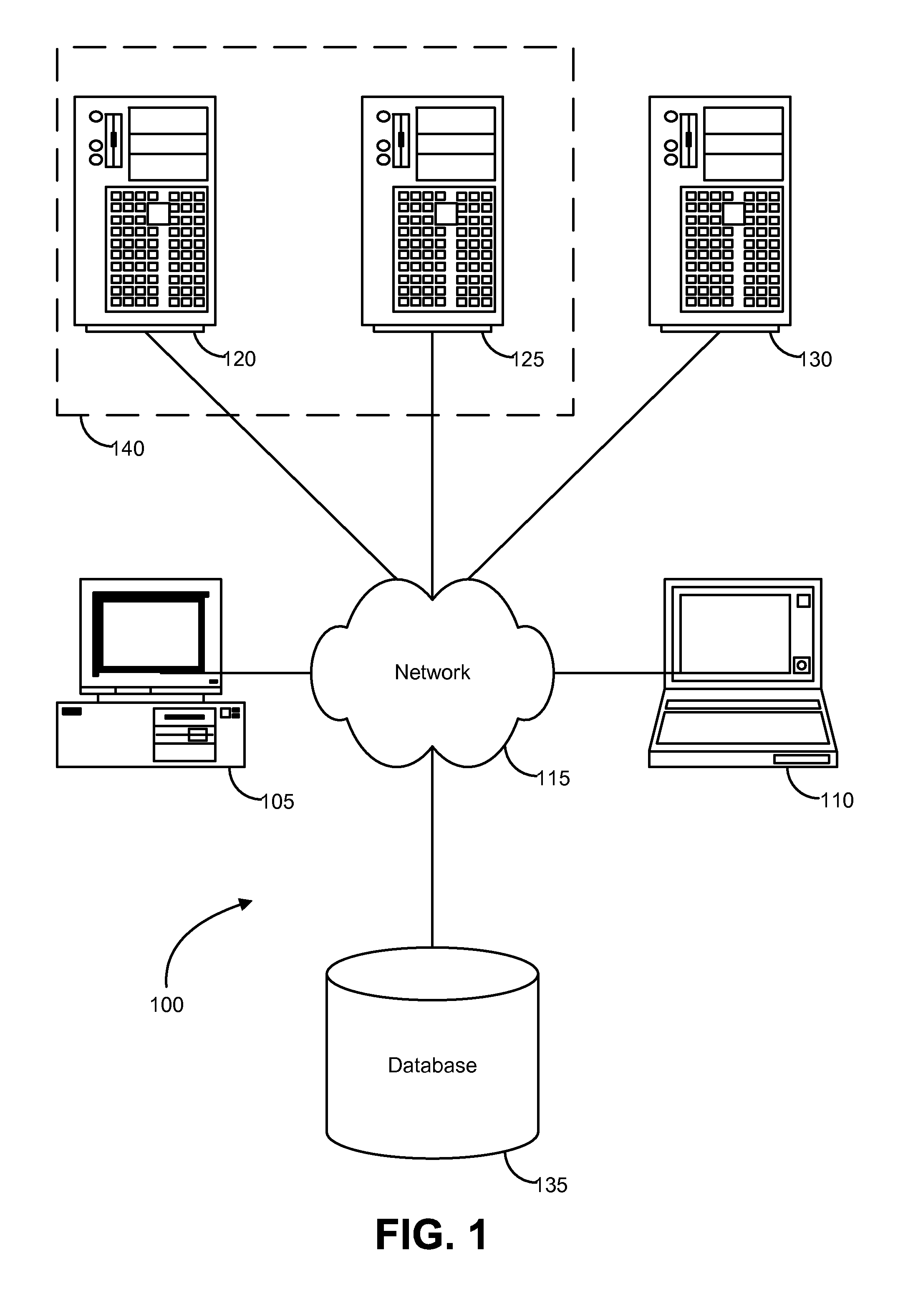
[0004]Embodiments of the invention provide systems and methods for orchestrating or coordinating interactions between different types of networks such as a legacy network and a next generation network. According to one embodiment, a method for coordinating interactions between different types of networks can comprise receiving at a service layer component a communication in a communication session from a first communication network. The communication can be in a first protocol. The communication can be translated from the first protocol to a second protocol with the service layer component, wherein the first protocol is different from the second protocol. One or more additional service layer components for providing at least one service in the communication session can be identified with an application dispatcher of the service layer component. The translated communication can be dispatched to the one or more additional service layer components from the application dispatcher.
[0005]For example, the first communication network can comprise a legacy network and the second communication network can comprise a next generation network. The service layer component can comprise a Service Delivery Platform (SDP) and the translated communication can be provided to a component of the next generation network. In such cases, providing the second communication to the component of the next generation network can comprise providing the second communication to a northbound interface of an enabler of the SDP. Additionally or alternatively, providing the second communication to the component of the next generation network can further comprise providing the second communication to a Session Initiation Protocol (SIP) servlet of the SDP and the second protocol comprises SIP. The one or more additional service layer components can comprise one or more enablers. For example, the one or more enablers can comprise one or more of a call control enabler, a media server control enabler, a messaging enabler, a charging enabler, a voice access enabler, and a presence enabler.
[0006]In another example, the first communication network can comprise a next generation network and the second communication network can comprise a legacy network. The service layer component can comprise a Service Delivery Platform (SDP) and the second communication can be provided to a component of the legacy network. In such cases, providing the second communication to the component of the legacy network can comprise providing the second communication to a northbound interface of an enabler of the SDP. The one or more additional service layer components can comprise one or more enablers. For example, the one or more enablers can comprise one or more of a call control enabler, a media server control ena

Problems solved by technology

However, these efforts have been limited to allowing the new services to operate on or interact with the legacy networks.
No approach has been developed to allow existing, legacy applications, i.e., applications written for a legacy network, to operate on or interact with the new, next generation networks or to coordinate or orchestrate such interactions.
Furthermore, replacing or modifying these legacy applications to operate on or interact with next generation networks can be costly and time consuming.
Such considerations can limit or slow the move to adopt next generation networks.

Method used


Image

  • Service level cross network coordinated interaction
  • Service level cross network coordinated interaction
  • Service level cross network coordinated interaction

Examples


Embodiment Construction

[0013]In the following description, for the purposes of explanation, numerous specific details are set forth in order to provide a thorough understanding of various embodiments of the present invention. It will be apparent, however, to one skilled in the art that embodiments of the present invention may be practiced without some of these specific details. In other instances, well-known structures and devices are shown in block diagram form.

[0014]The ensuing description provides exemplary embodiments only, and is not intended to limit the scope, applicability, or configuration of the disclosure. Rather, the ensuing description of the exemplary embodiments will provide those skilled in the art with an enabling description for implementing an exemplary embodiment. It should be understood that various changes may be made in the function and arrangement of elements without departing from the spirit and scope of the invention as set forth in the appended claims.

[0015]Specific details are ...


PUM


Abstract

Embodiments of the invention provide systems and methods for orchestrating or coordinating interactions between different types of networks such as a legacy network and a next generation network. According to one embodiment, a method for coordinating interactions between different types of networks can comprise receiving at a service layer component a communication in a communication session from a first communication network. The communication can be in a first protocol. The communication can be translated from the first protocol to a second protocol with the service layer component, wherein the first protocol is different from the second protocol. One or more additional service layer components for providing at least one service in the communication session can be identified with an application dispatcher of the service layer component. The translated communication can be dispatched to the one or more additional service layer components from the application dispatcher.

Description

CROSS-REFERENCES TO RELATED APPLICATIONS[0001]The present application claims benefit under 35 USC 119(e) of U.S. Provisional Application No. 61 / 301,822, filed on Feb. 5, 2010 by Maes and entitled “Service Level Cross Network Coordinated Interaction,” of which the entire disclosure is incorporated herein by reference for all purposes.BACKGROUND OF THE INVENTION[0002]Embodiments of the present invention relate generally to methods and systems for supporting interactions in communication sessions and more particularly to orchestrating or coordinating interactions between different types of networks.[0003]New networks, i.e., “next generation networks,” such as Internet Protocol (IP) Multimedia Subsystem (IMS) networks and various IP-based networks such as the Internet have been and are being developed to support communication sessions and services related thereto. Various approaches have been developed to integrate these networks and services with various types of “legacy” networks such...

Claims


Application Information

Patent Timeline
IPC IPC(8): G06F15/16
CPCH04L65/104H04L69/08H04L65/80H04L65/1006H04L65/1104
Inventor MAES, STEPHANE H.
Owner ORACLE INT CORP
Learn More