Crankshaft-link piston machine

Inactive Publication Date: 2011-08-18
ZAKHAROV EVGENY NIKOLAEVICH
View PDF11 Cites 3 Cited by
  • Summary
  • Abstract
  • Description
  • Claims
  • Application Information

AI Technical Summary

Benefits of technology

[0006]The technical result of the claimed invention consists in the increased operational reliab

Problems solved by technology

The disadvantages of the known machine are considerable radial dimensions of the machine (in the direction of the cylinder axis) due to allocation of separate successive zones: for movement of the link having a considerable width, for the rod guide and for the piston motion (cylinder).
Besides, the rod and its guide possess insufficient rigidity

Method used


Image

  • Crankshaft-link piston machine
  • Crankshaft-link piston machine
  • Crankshaft-link piston machine

Examples


Example

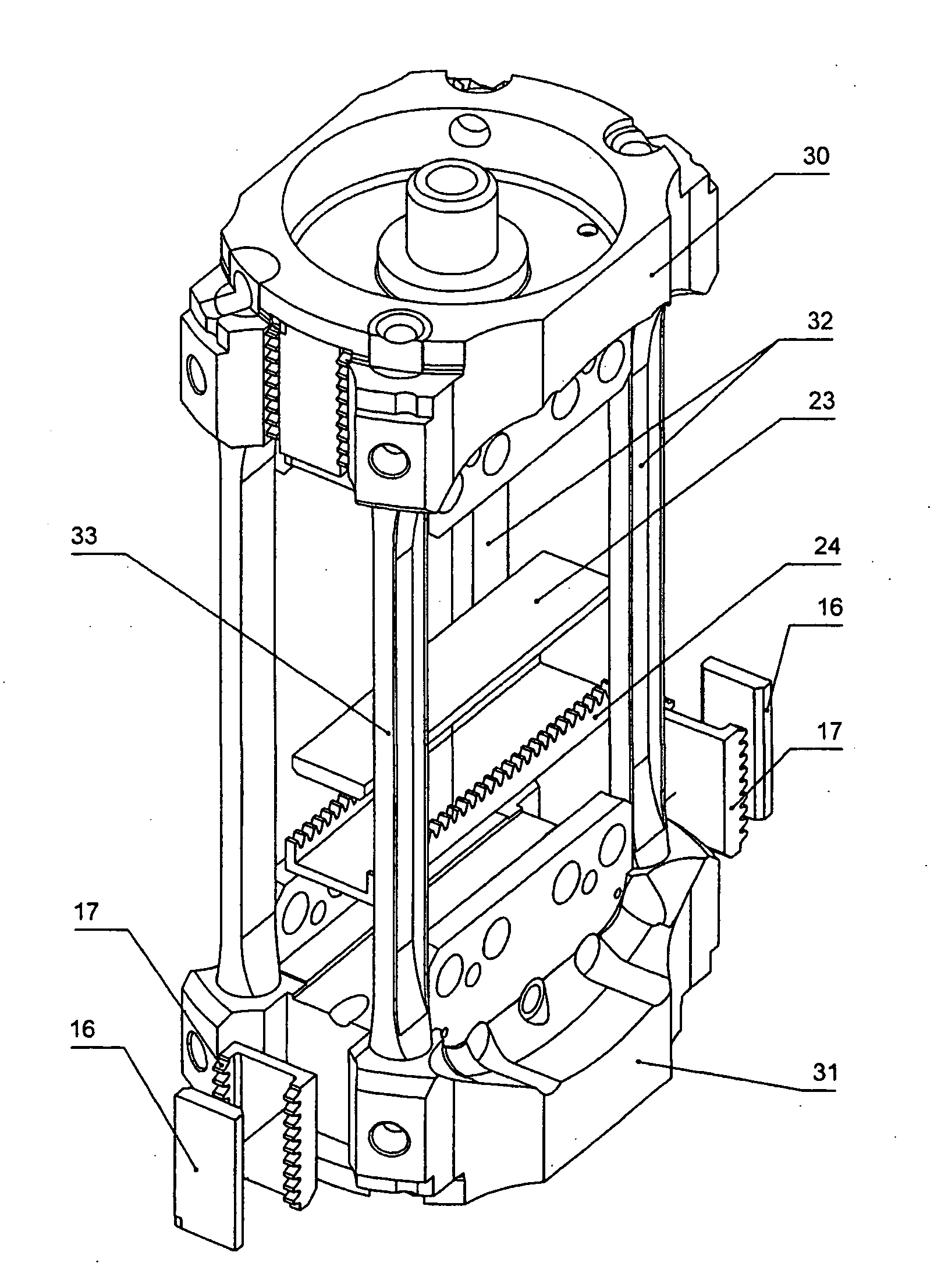
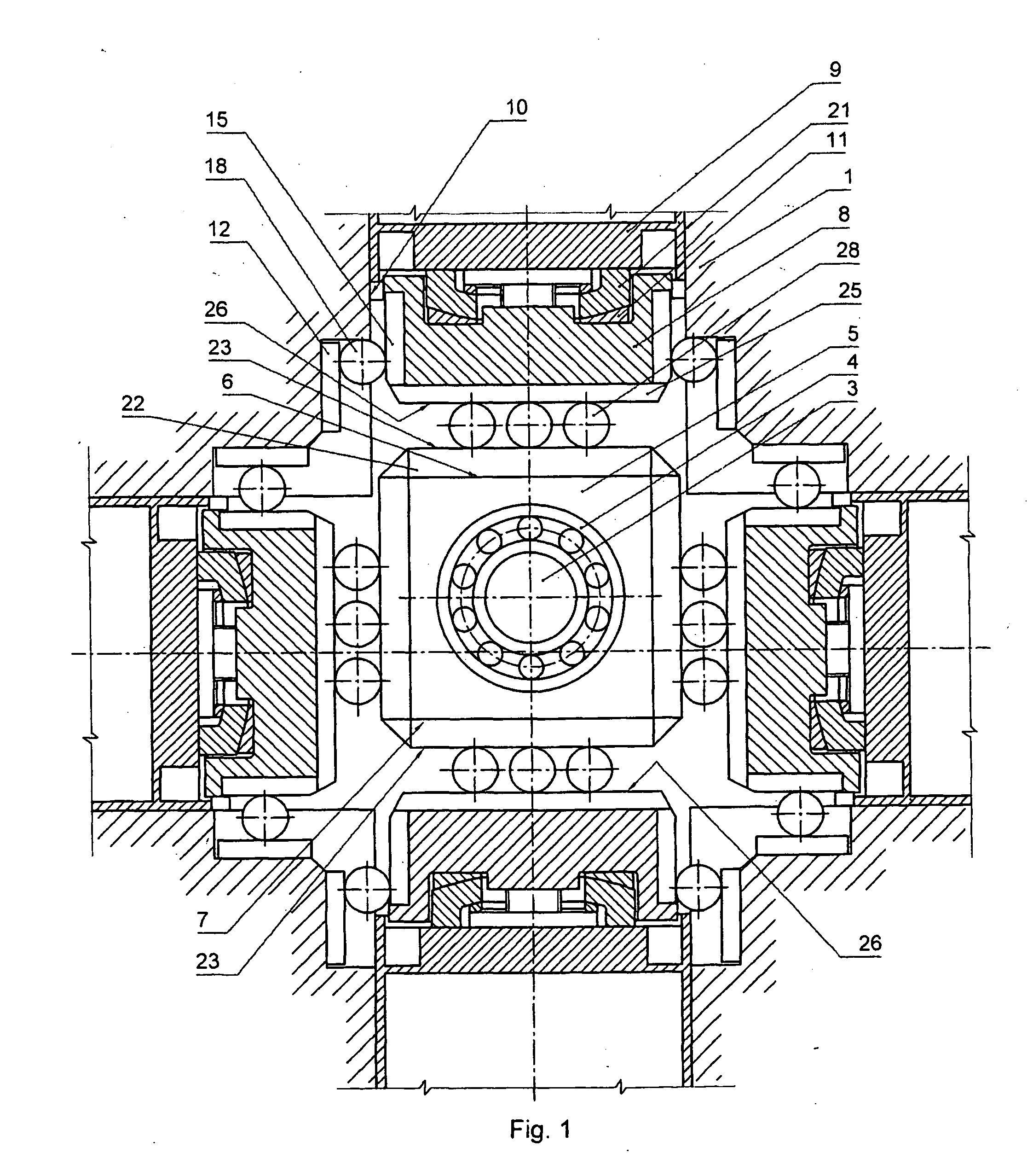
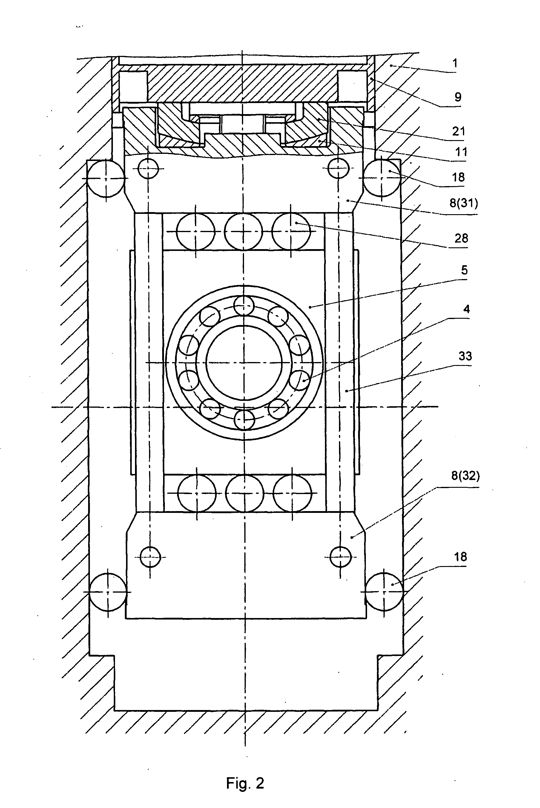
[0022]The crankshaft-link machine consists of case 1, which accommodates crankshaft 2 with crank 3, mounting, through bearing 4, slide block 5 (slider). Opposite work surfaces 7 and 8 of slide block 5 interact with the surfaces of link 8 coupled with piston 9 reciprocating in cylinder 10. Piston 9 and link 8 are interconnected by means of a hinge assembly with flat hinge 11, enabling piston 9 to self-align along the surface of cylinder 10. Radial clearance in hinge 11, made, for example, in the form of a bayonet connection, enables piston 9 to travel relative to link 8 in any direction in the plane crossing the longitudinal axis of cylinder 10. The surface of case 1 mounts support elements 12 with contact surfaces 13 and toothed racks 14, while the surfaces of link 8 mount support elements 15 with contact surfaces 16 and toothed racks 17. Accommodated in-between contact surfaces 13 and 16 are rollers 18 provided with synchronizing toothed wheels 19 engaged with toothed racks 14 and ...


PUM


Abstract

The invention relates to mechanical engineering, in particular to piston machines and mechanisms for converting the movement of the pistons thereof into shaft rotation. The technical result of the invention involves increasing the operational reliability, extending the service life, improving the specific mass and dimensional characteristics and enhancing the effectiveness of a machine. The essence of the invention is that the piston and the crank of a piston machine are interconnected by means of a hinged joint with at least a flat hinge which enables the piston to self-center along the surface of a cylinder owing to the movement of the piston with respect to the crank in any direction on a plane that intersects the longitudinal axis of the cylinder. The surfaces of the crank that take up reactive torque are constricted by rollers with synchronized toothed wheels.

Description

FIELD OF THE INVENTION[0001]The invention relates to the sphere of machine building, in particular to the piston machines and mechanisms converting piston reciprocation into shaft rotation.BACKGROUND ART[0002]As is known there exists a crankshaft-link piston machine consisting of a case accommodating a crankshaft with one crank which mounts, through a bearing, a slide block; the opposite work surfaces of the slide block interact with the surfaces of the link coupled with a piston reciprocating inside a cylinder secured to the machine case (Ref. Artobolevsky, Mechanisms in Current Technology, Moscow, Nauka, Volume 2, p. 23, 1979).[0003]The disadvantages of the known machine are considerable radial dimensions of the machine (in the direction of the cylinder axis) due to allocation of separate successive zones: for movement of the link having a considerable width, for the rod guide and for the piston motion (cylinder). Besides, the rod and its guide possess insufficient rigidity to tak...

Claims


Application Information

Patent Timeline
IPC IPC(8): F01B9/00
CPCF01B9/047Y10T74/18248F01B1/0644F01B9/023F01B1/062
Inventor ZAKHAROV, EVGENY NIKOLAEVICH
Owner ZAKHAROV EVGENY NIKOLAEVICH
Why Eureka
Try Eureka