
Process medium-controlled regulating valve

Active Publication Date: 2018-05-24
GROHE
View PDF3 Cites 1 Cited by
  • Summary
  • Abstract
  • Description
  • Claims
  • Application Information

AI Technical Summary

Benefits of technology

The present invention aims to provide a simple process medium-controlled regulating valve that can improve operational reliability.

Problems solved by technology

Over the course of the operating life, the pilot line can become clogged with impurities, for example, lime deposits.
As a result, the lime deposits on the inner circumference of the pilot line and on the cleaning wire element can be removed only insufficiently.

Method used


Image

  • Process medium-controlled regulating valve
  • Process medium-controlled regulating valve
  • Process medium-controlled regulating valve

Examples


Embodiment Construction

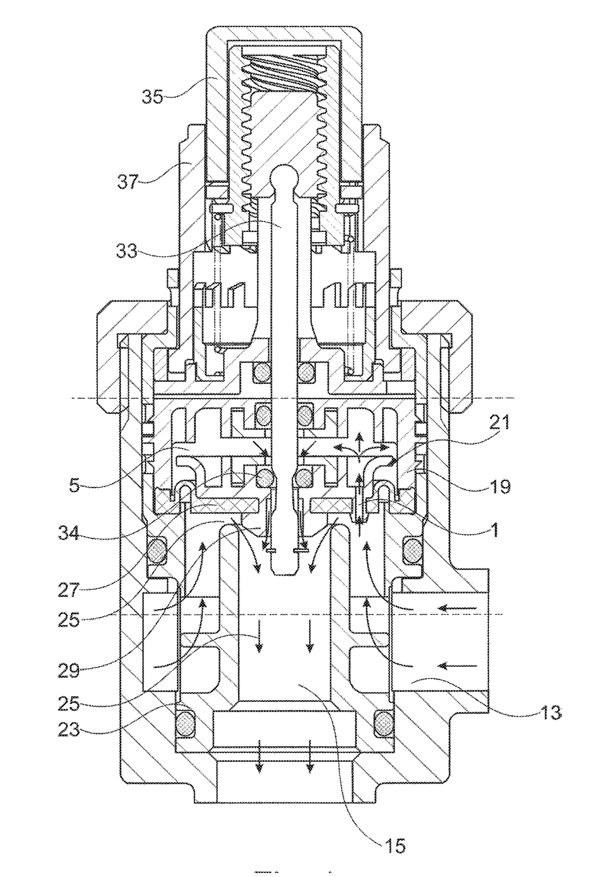
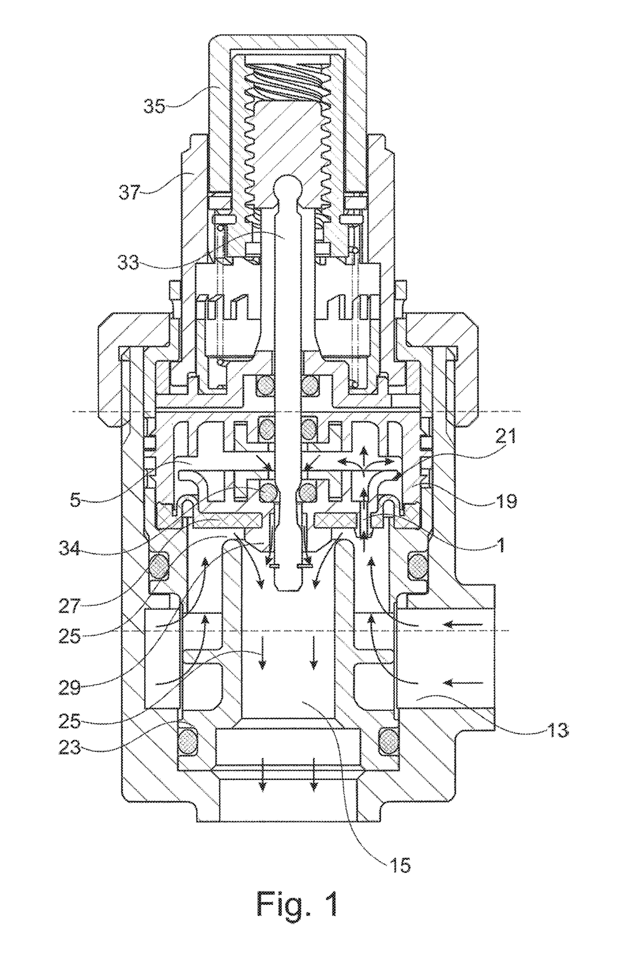
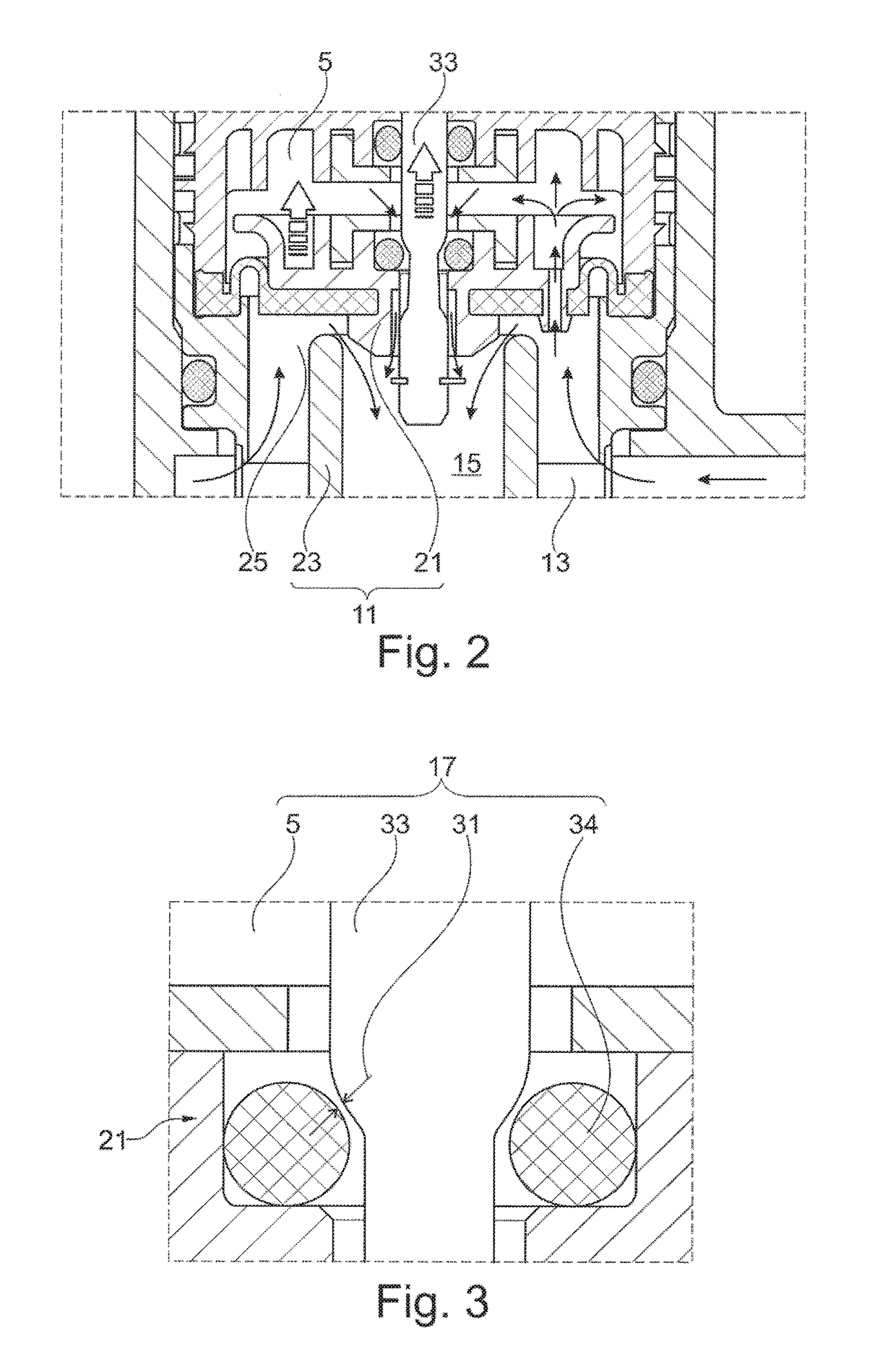
[0027]The structure and the basic operation of the process medium-controlled regulating valve will be described first for easier understanding of the invention with use of FIGS. 1 to 3. For reasons of clarity, a cleaning wire 3 guided through a pilot line 1 and a helical compression spring 41 disposed in a control chamber 5 are omitted in FIGS. 1 to 3 and shown only in FIGS. 4 and 5.

[0028]The regulating valve shown in FIG. 1 comprises a main valve 11 (FIG. 2), with which a liquid throughflow between an inlet chamber 13 and an outlet chamber 15 can be regulated, and a pilot valve 17 controlling main valve 11 (FIG. 3), which can be used as a control component for main valve 11. Main valve 11 shown in FIG. 1 is made up of a main valve piston 21, with an adjustable stroke in the axial direction in a valve housing 19, and of a main valve seat 23 which interacts therewith. In FIG. 1, main valve piston 21 is shown in its open position, as a result of which a valve gap 25 is exposed for thr...


PUM


Abstract

A process medium-controlled regulating valve for a liquid throughflow regulator, having a main valve, a pilot valve for controlling a main valve piston, a pilot valve piston which closes the pressure relief line in a closed position, a cleaning wire element which is stationary in the axial direction is guided with hole tolerance through the pilot line, and the pilot line can be moved along the cleaning wire element, which is guided therein, during a stroke adjustment of the main valve piston. The cleaning wire element has an actuating contour which, at least during the stroke adjustment, can be brought into sliding contact with a counter-contour formed on the main valve piston, with the build-up of a transverse force which acts on the cleaning wire element.

Description

[0001]This nonprovisional application is a continuation of International Application No. PCT / EP2016 / 001186, which was filed on Jul. 11, 2016, and which claims priority to German Patent Application No. DE 10 2015 009 106.9, which was filed in Germany on Jul. 17, 2015, and which are both herein incorporated by reference.BACKGROUND OF THE INVENTIONField of the Invention[0002]The present invention relates to process medium-controlled regulating valve for a liquid throughflow regulator.Description of the Background Art[0003]A process medium-controlled regulating valve of this type can be used, for example, in a plumbing fixture by means of which the water outflow, for example, to a bathtub drain, a handheld shower head, or an overhead shower head, can be turned on or off. In the process medium-controlled regulating valve, the inlet-side water pressure is conducted via a pilot line to a pilot valve, which forms a control component for a main valve. The pilot valve uses a control chamber a...

Claims


Application Information

Patent Timeline
IPC IPC(8): F16K31/385F16K31/383F16K21/12F16K31/34F16K31/122
CPCF16K31/3855F16K31/383F16K21/12F16K31/34F16K31/1221F16K17/105F16K31/426F16K31/52491
Inventor BUCHMUELLER, JANIKPALMER, NICOLEBISCHOFF, BERND
Owner GROHE
Learn More