Ground fault detection and interrupt system

Active Publication Date: 2017-06-22
GE ENERGY POWER CONVERSION TECH
View PDF1 Cites 0 Cited by
  • Summary
  • Abstract
  • Description
  • Claims
  • Application Information

AI Technical Summary

Benefits of technology

The patent text describes a need for methods to automatically recover from faults in high power inverter systems, such as solar PV arrays connected to the grid. This is important because it can reduce lost electrical power production and increase reliability. The approach involves partitioning the system into zones, where fault monitoring and reconnection occurs to minimize downtime. The system can continue operating even if a fault occurs in one of the zones, as long as other zones are still operating correctly. Overall, this method helps ensure a system can still produce energy even if there are multiple faults.

Problems solved by technology

Inverter operability, therefore, can be critical.
Inverters, however, can be particularly vulnerable, and rendered inoperable, by a variety of different fault conditions.
When inverters become inoperable, especially when used in PV array energy systems, the result can be lost production, or worse: lost electrical generation.
These long cable runs increase the likelihood of faults, an increase the difficulty of identifying faults when they occur.
Faults may also occur internal to the PV panels.
Given the long cable runs, large numbers of connection points, and the possibility of faults occurring within the PV panels, the chances of a ground fault outside of the inverter can be relatively high.
In high power solar applications, the number of PV array circuits increases and the risks associated with downtime increases proportionally.
Due to this isolation, a ground fault event can go undetected by other protection devices, such as fuses and circuit breakers, as a single fault will not usually activate these protection devices.
These larger number of inverters come at considerably increased costs due to the higher number of systems and supporting infrastructure
Since the location of the faults cannot be easily determined in conventional systems, continued system operation of these systems, after the occurrence of faults, is nearly impossible.

Method used


Image

  • Ground fault detection and interrupt system
  • Ground fault detection and interrupt system
  • Ground fault detection and interrupt system

Examples


Embodiment Construction

[0008]Given the aforementioned deficiencies, a need exists for methods of automatic system recovery from faults that can greatly reduce lost electrical power production and increase operational reliability in high power inverter systems.

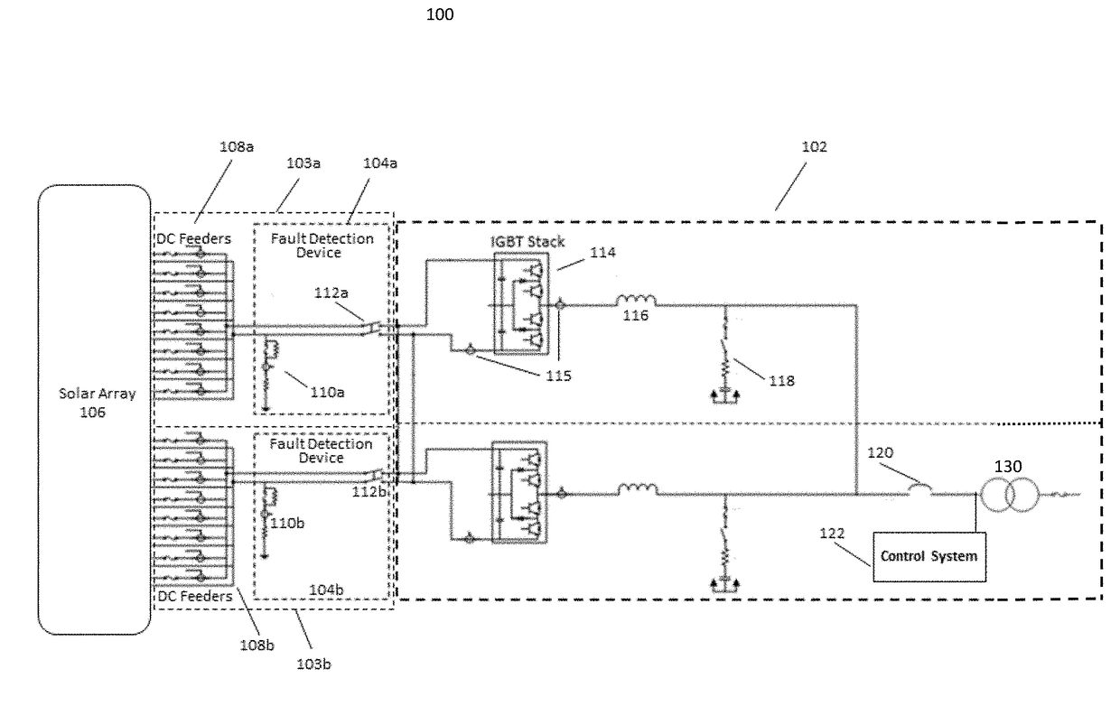
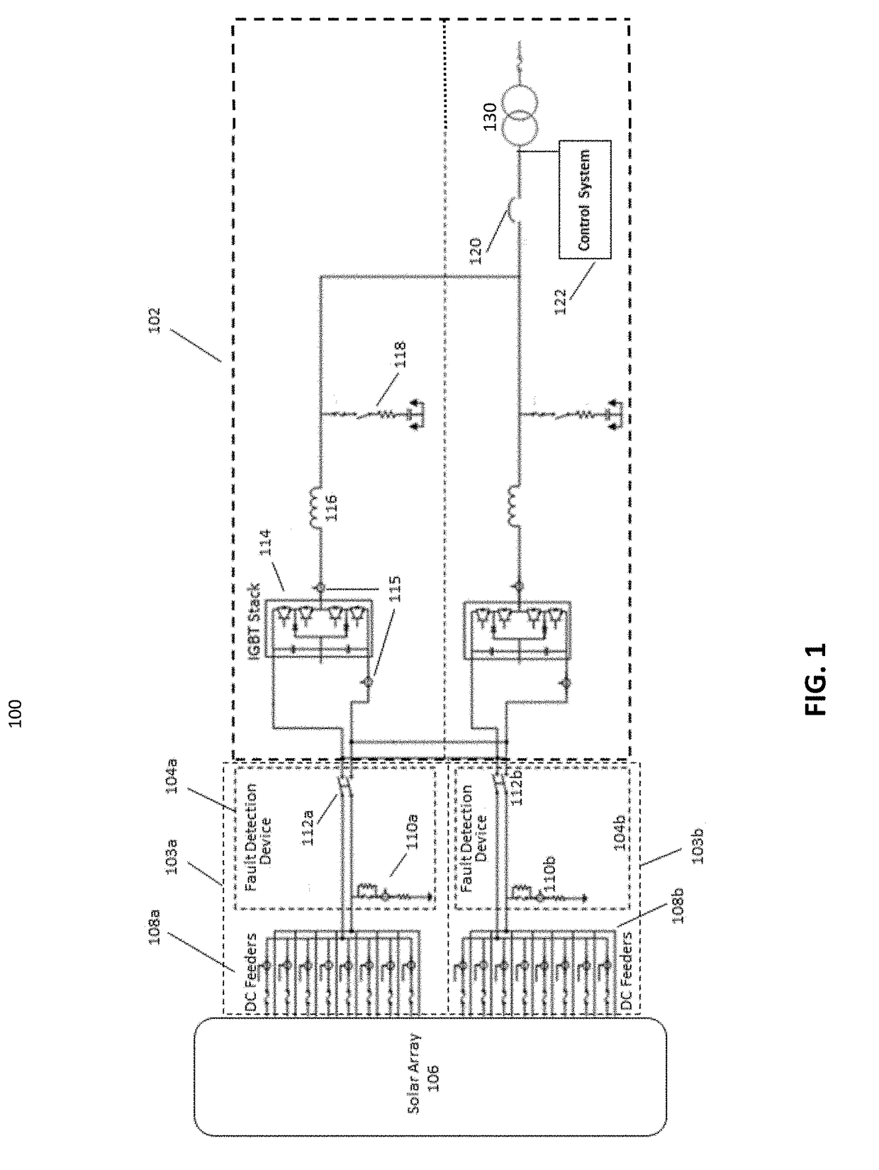
[0009]In certain circumstances, embodiments of the present invention provide a fault isolation apparatus for an inverter configured for coupling to an external power supply. The apparatus includes a plurality of fault detection devices, each configured to (i) complete an electrical path between the inverter and the external power supply and (ii) detect a fault along its respective electrical path. The apparatus also includes a controller configured to instruct the fault detection device to complete its respective electrical path only when the path is devoid of the detected fault.

[0010]With higher operational reliability, users can continue operating systems, such as solar PV arrays couple to the electric grid, when faults occur. Such an approach can ...


PUM


Abstract

Provided is a fault isolation apparatus for an inverter configured for coupling to an external power supply. The apparatus includes a plurality of fault detection devices, each configured to (i) complete an electrical path between the inverter and the external power supply and (ii) detect a fault along its respective electrical path. The apparatus also includes a controller configured to instruct the fault detection device to complete its respective electrical path only when the path is devoid of the detected fault.

Description

I. FIELD OF THE INVENTION[0001]The present invention generally relates to fault detection in inverter systems. More particularly, the present invention relates to fault detection and isolation in inverters connected to the electrical grid.II. BACKGROUND OF THE INVENTION[0002]Inverters, and inverter based systems, are used in a variety of applications. By way of example, inverters are commonly used for converting direct current (DC) output from a photovoltaic (PV) solar array into alternating current (AC). This AC current can be supplied to the electrical grid, or used for other purposes, such as standalone electrical networks. Inverter operability, therefore, can be critical. Inverters, however, can be particularly vulnerable, and rendered inoperable, by a variety of different fault conditions.[0003]When inverters become inoperable, especially when used in PV array energy systems, the result can be lost production, or worse: lost electrical generation. Solar applications inherently ...

Claims


Application Information

Patent Timeline
IPC IPC(8): H02H3/16G01R31/02
CPCH02H3/16G01R31/026G01R31/025H02H3/06H02H7/1222H02H7/20Y02E10/56G01R31/42G01R31/52G01K7/00H02H5/047H03K17/56
Inventor FRYE, DAVID EVERETTSTONE, PHILIP EDGAR CRAPSEOPILA, DANIEL FRANCISWAGONER, ROBERT GREGORYPANT, SIDDHARTHDAWANDE, SHRUTISH
Owner GE ENERGY POWER CONVERSION TECH
Why Eureka
Try Eureka