Traffic management system

a traffic management system and traffic management technology, applied in the field of traffic management systems, can solve the problems of static traffic signs, inability to respond quickly and efficiently to changing roadway conditions, and numerous deficiencies of traditional roadway signs

Inactive Publication Date: 2011-08-18
LOISELLE VINCENT +1
View PDF9 Cites 45 Cited by
  • Summary
  • Abstract
  • Description
  • Claims
  • Application Information

AI Technical Summary

Problems solved by technology

Unfortunately, traditional roadway signs are unable to respond to these changing roadway conditions quickly and efficiently.
However, in practice, traditional traffic signs that provide information to motorists about upcoming roadway conditions face numerous deficiencies.
Firstly, static traffic signs that warn about upcoming roadway conditions, such as slippery roads, become invisible to motorists over time.
This results in the traffic sign being ineffective and useless at times when the roadways are in fact slippery.
Secondly, a single traffic sign (which could be a static traffic sign, a variable-message digital display or a multi-panel traffic sign) that provides information relating to an upcoming roadway condition, is not always sufficient for conveying the relevant information to motorists.
There is also the chance that a motorist is distracted as he / she drives past the sign, and misses the message altogether.
In addition, traditional traffic signs are not always suitable for providing relevant up-to-date information.
Even in the case of variable-message digital display screens, there is often a delay between what is occurring in traffic, and what is being displayed by the traffic sign.
This creates delays in updating the messages being displayed by the traffic sign.

Method used


Image

  • Traffic management system
  • Traffic management system
  • Traffic management system

Examples


first embodiment

[0086]In a first embodiment, the environmental sensor 78 is operative for taking periodic humidity readings, such as every hour or half hour for example, and providing those humidity readings to the processing entity 70. This may be done automatically by the environmental sensor 78, or may be done in response to a request by the processing entity 70. In both of the above circumstances, the environmental sensor 78 is operative for providing the processing entity 70 with a humidity reading indicative of a humidity level detected.

second embodiment

[0087]In a second embodiment, the environmental sensor 78 is operative for transmitting a signal to the processing entity 70 when a pre-established humidity level is detected. In such a case, upon detection of the pre-established humidity level, the environmental sensor 78 is triggered to issue a signal to the processing entity 70. The signal issued by the environmental sensor 78 to the processing entity 70 may simply be indicative that the pre-established humidity level has been detected.

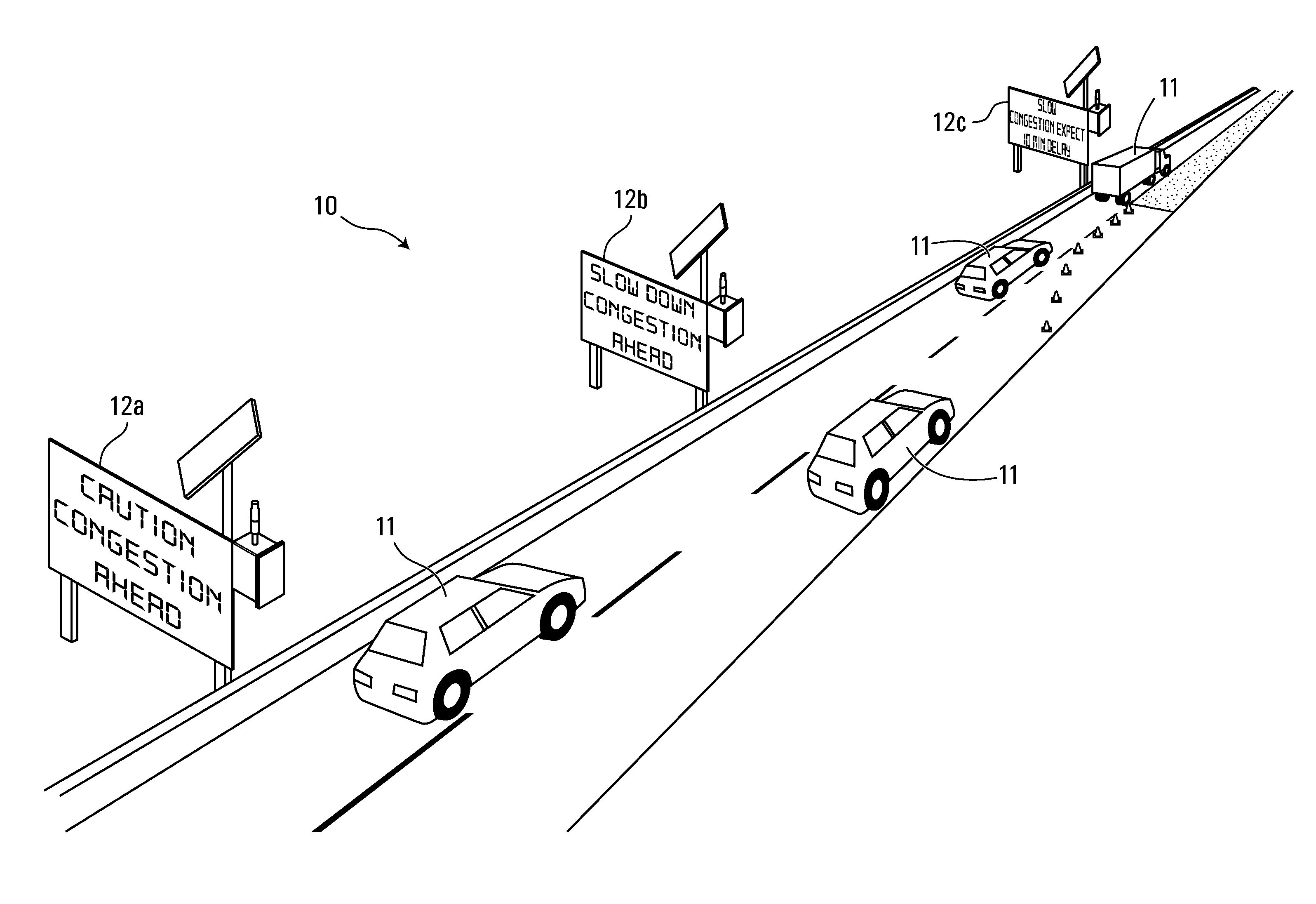
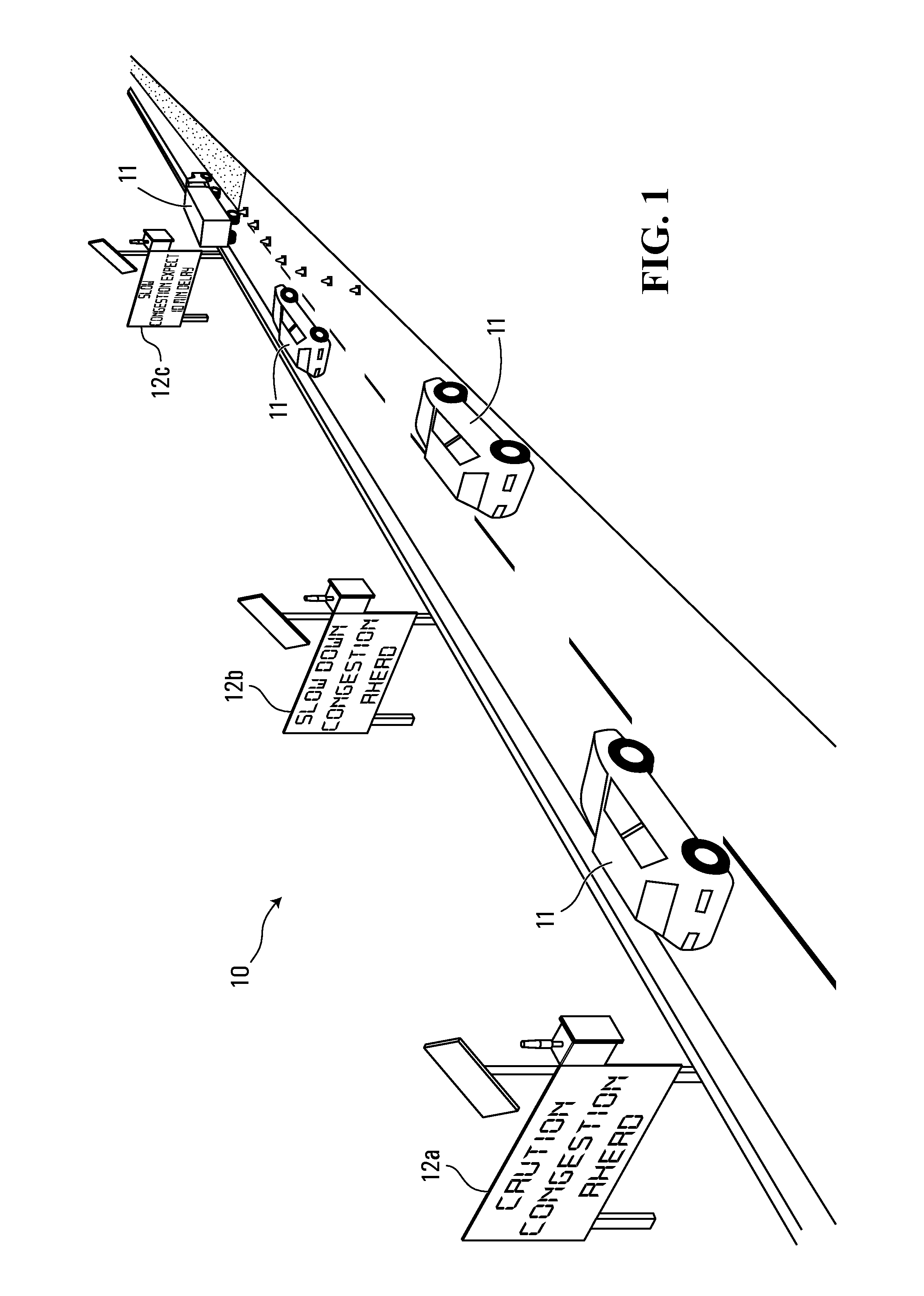
[0088]In the case where the environmental sensor 78 is operative for detecting traffic congestion, it may provide signals indicative of traffic level at periodic time intervals, or it may instead, provide a signal to the processing entity 70 when a pre-established traffic level has been detected. Although the functioning of environmental sensors used with the traffic management system 10 of FIG. 1 was not described in detail, any environmental sensors used with the traffic management system 10 coul...


PUM


Abstract

A method and system for managing traffic via a plurality of traffic signs positioned sequentially along a stretch of roadway. Each traffic sign in the plurality of traffic signs is capable of displaying more than one different traffic message. The method comprises receiving at a first traffic sign in the plurality of traffic signs a wireless control signal indicative that the plurality of traffic signs are to display a new message, and then causing each traffic sign in the plurality of traffic signs to display a new traffic message. The new traffic messages displayed by the plurality of traffic signs provide information relating to a roadway condition downstream of at least the front-most traffic sign in the plurality of traffic signs.

Description

CROSS REFERENCE TO RELATED APPLICATIONS[0001]This application claims the benefit under 35 USC §119(e) of U.S. provisional patent application Ser. No. 61 / 303,857 filed Feb. 12, 2010. The contents of the above-mentioned patent application are incorporated herein by reference.FIELD OF THE INVENTION[0002]The present invention relates generally to the field of traffic management systems and specifically to traffic management systems that comprise a plurality of traffic signs capable of acquiring a condition for providing information to motorists regarding upcoming roadway conditions.BACKGROUND OF THE INVENTION[0003]In the field of traffic management, it is desirable to provide information to motorists in a manner that quickly adapts to changing roadway conditions. Providing relevant, real-time information to motorists allows motorists to adjust their driving behaviour according to the upcoming roadway condition, thereby improving roadway safety. For example, when construction is being pe...

Claims


Application Information

Patent Timeline
Patent Type & Authority Applications(United States)
IPC IPC(8): G08G1/095
CPCG08G1/0104G09F15/0006G09F9/33G08G1/09
Inventor LOISELLE, VINCENTSEGUIN, MARC-ANDRE
Owner LOISELLE VINCENT
Why Eureka
Try Eureka