Method for imaging workpiece surfaces at high robot transfer speeds with reduction or prevention of motion-induced distortion

a technology of workpiece surfaces and robots, which is applied in the field of reducing or preventing motion-induced distortion of workpiece surfaces, can solve the problems of affecting the accuracy of in-situ measurement of the width or concentricity of the film edge exclusion annular region, and affecting the accuracy of in-situ measurement of the width or concentri

Active Publication Date: 2011-08-18
APPLIED MATERIALS INC
View PDF10 Cites 9 Cited by
  • Summary
  • Abstract
  • Description
  • Claims
  • Application Information

AI Technical Summary

Benefits of technology

A method is provided for obtaining an image of a workpiece in a processing system including a robot for transporting a workpiece to and from the processing chambers of the system along a workpiece transfer path. The method includes capturing, at variable frame rate, successive frames of an elongate stationary field of view transverse to a transit path portion of the workpiece transit path while the workpiece is transported along the transit path portion by the robot. The method further includes illuminating the transit path portion with an elongate illumination pattern transverse to the transit path portion during t...

Problems solved by technology

Any error or inconsistency in the placement of the wafer on the wafer support pedestal in the reactor chamber can cause the film layer annular region boundary to be non-concentric with the wafer edge.
However, accurate in-situ measurement of the width or concentricity of the film edge exclusion annular region has been hampered...

Method used


Image

  • Method for imaging workpiece surfaces at high robot transfer speeds with reduction or prevention of motion-induced distortion
  • Method for imaging workpiece surfaces at high robot transfer speeds with reduction or prevention of motion-induced distortion
  • Method for imaging workpiece surfaces at high robot transfer speeds with reduction or prevention of motion-induced distortion

Examples


Embodiment Construction

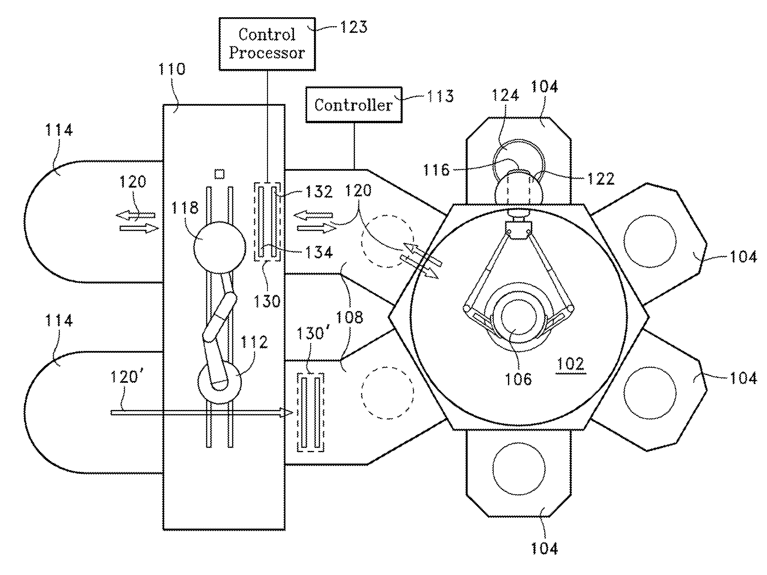
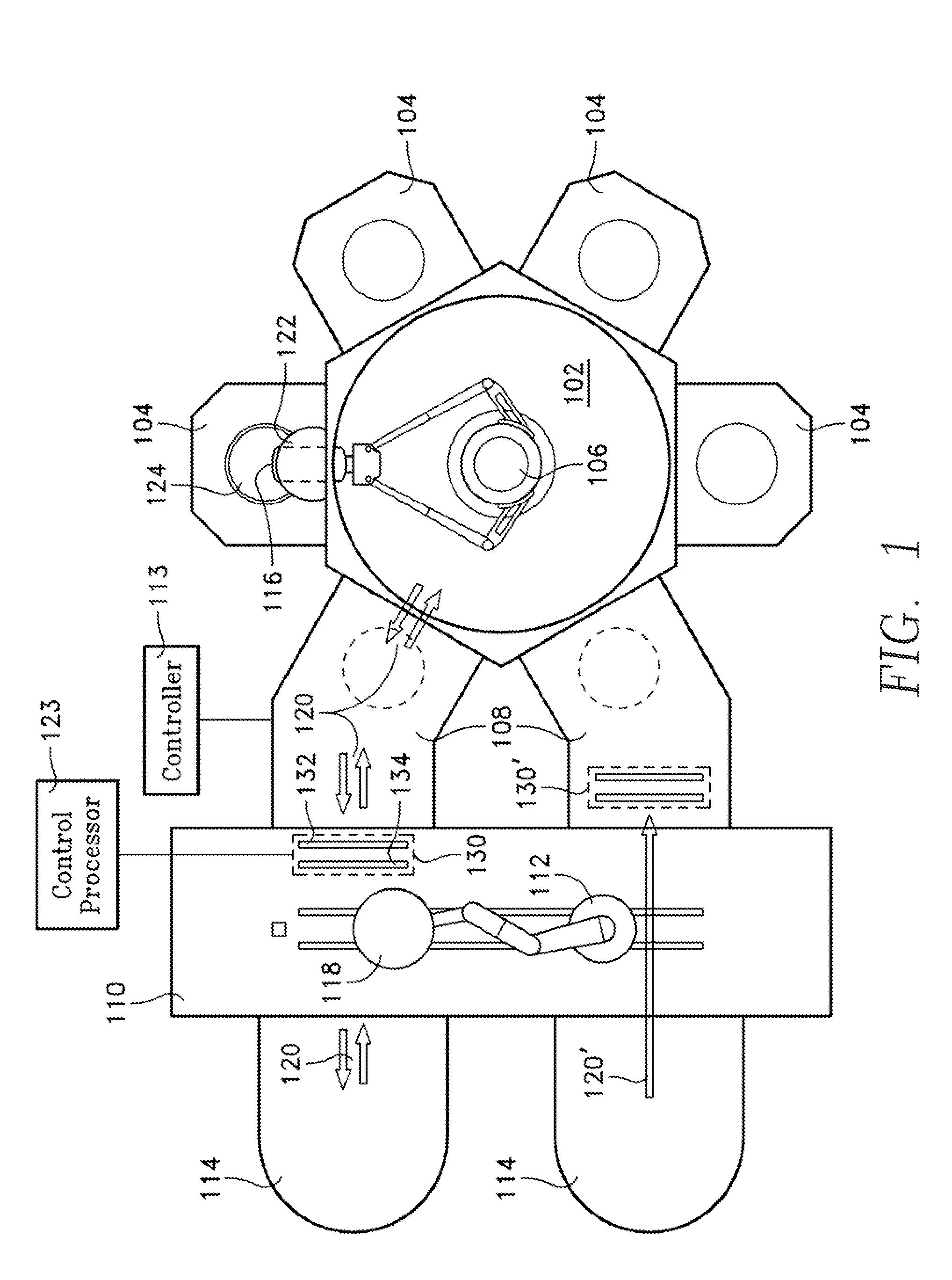
FIG. 1 depicts a wafer processing tool that includes a vacuum transfer chamber 102 coupled to four wafer processing chambers 104, all held at sub-atmospheric pressure. A vacuum robot 106 transfers individual wafers between any one of the processing chambers 104 and any one of two load lock chambers 108. A factory interface 110 is at atmospheric pressure, and includes an atmospheric robot 112 for transferring a wafer between one or more cassettes 114 and the load lock chamber 108. The load lock chamber 108 provides a transition between the atmospheric pressure of the factory interface 110 and the vacuum of the vacuum transfer chamber 102. The vacuum robot 106 holds each wafer on a vacuum robot blade 116, while the atmospheric robot 112 holds each wafer on an atmospheric robot blade 118. The robots 106, 112 move each wafer along a wafer transit path 120 through the factory interface at a high speed of over 1 meter per second, e.g., about 1.7 meters per second. The robots 106, 112 are ...


PUM


Abstract

A method is provided for imaging a workpiece by capturing successive frames of an elongate stationary field of view transverse to a workpiece transit path of a robot, while the workpiece is transported by the robot. The robot transit path is illuminated with an elongate illumination pattern transverse to the transit path to obtain a workpiece image of successive frames. Motion-induced image distortion is prevented or reduced adjusting the camera frame rate in real time in proportion to changes in robot velocity profile of the workpiece along the transit path.

Description

BACKGROUNDIn semiconductor processing, systems are employed that can process a number of workpieces simultaneously. The workpieces may be semiconductor wafers for fabrication of ultra large-scale integrated circuits or display panels or solar arrays, or the workpieces may be masks employed in photolithography. For semiconductor wafers, the wafers may be robotically transferred at high speed (e.g., 1.7 meters per second) through a factory interface for transfer to any one of a number of parallel processing chambers or modules. The centering of the wafer on the wafer support pedestal within each processing chamber is critical and must be consistent. For example, one of the processing chambers may be employed to deposit a film on the wafer surface, while a small annular region at the wafer periphery is masked to prevent film deposition in the peripheral region. This annular peripheral region may also be referred to as the film annular exclusion region or zone. Film deposition in the an...

Claims


Application Information

Patent Timeline
IPC IPC(8): H04N7/18
CPCH01L21/67253H01L21/681H01L21/67288B25J13/087G06T5/006H01L21/67742G06T2207/30148G06V10/243
Inventor RAVID, ABRAHAMEGAN, TODDLINGEL, KAREN
Owner APPLIED MATERIALS INC
Why Eureka
Try Eureka