Exposure apparatus, exposing method, maintenance method and device fabricating method

a technology of exposing apparatus and fabricating method, which is applied in the direction of photomechanical treatment, printing, instruments, etc., can solve problems such as the production of defective devices, and achieve the effect of preventing exposure failures and preventing defective devices

Inactive Publication Date: 2011-08-18
NIKON CORP
View PDF17 Cites 6 Cited by
  • Summary
  • Abstract
  • Description
  • Claims
  • Application Information

AI Technical Summary

Benefits of technology

[0015]Aspects of the present invention can prevent exposure failures from occurring. In addition, the present invention makes it possible to prevent defective devices from being produced.

Problems solved by technology

In the immersion exposure apparatus, if a member that contacts the liquid is contaminated, then exposure failures, such as defects in the pattern formed in the substrate, might occur and, as a result, defective devices might be produced.

Method used


Image

  • Exposure apparatus, exposing method, maintenance method and device fabricating method
  • Exposure apparatus, exposing method, maintenance method and device fabricating method
  • Exposure apparatus, exposing method, maintenance method and device fabricating method

Examples


first embodiment

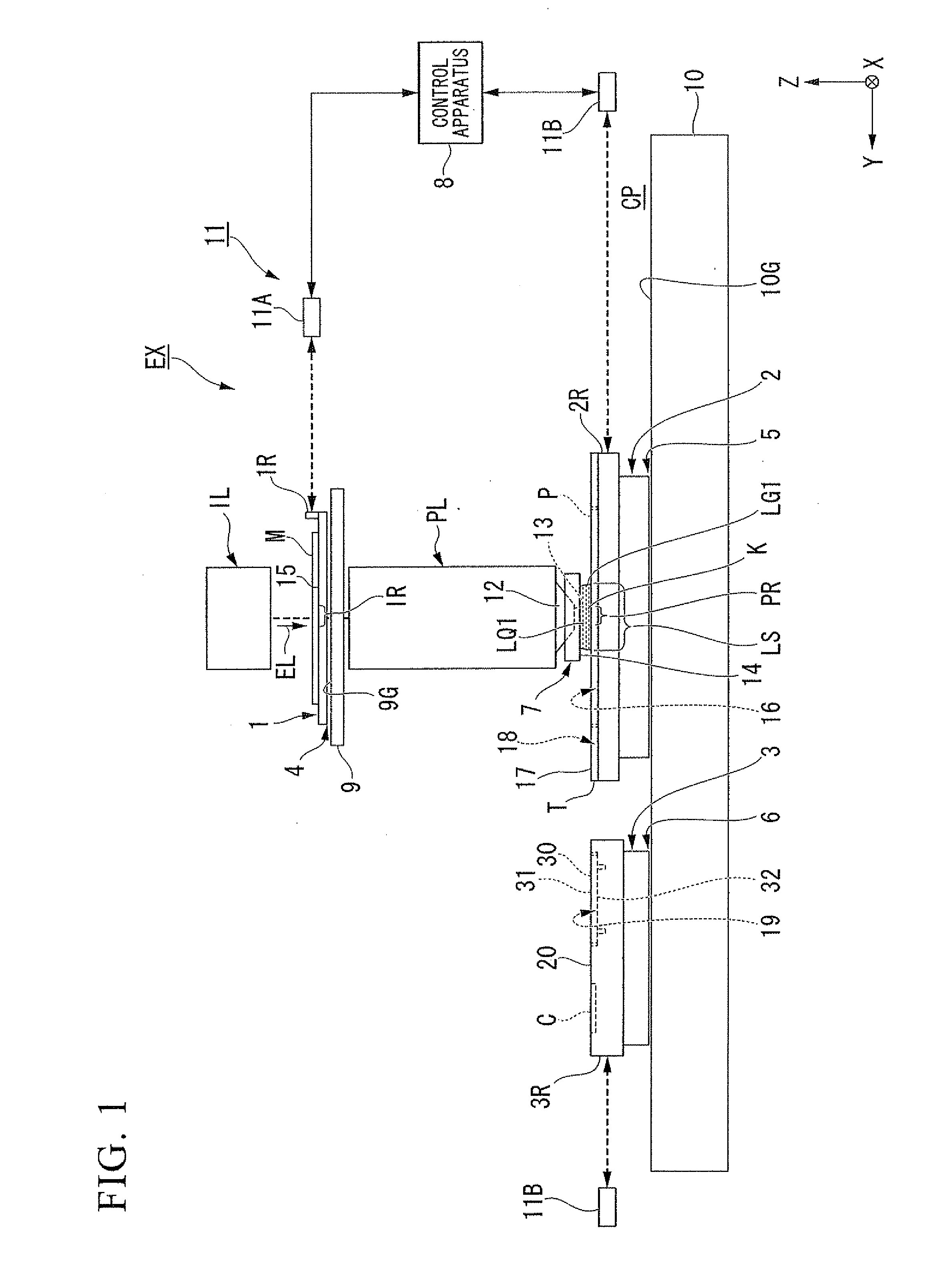
[0043]A first embodiment will now be explained. FIG. 1 is a schematic block diagram that shows one example of an exposure apparatus EX according to a first embodiment. The exposure apparatus EX of the present embodiment is an immersion exposure apparatus that exposes a substrate P with exposure light EL that transits a first liquid LQ1. In the present embodiment, an immersion space LS is formed such that at least part of the optical path of the exposure light EL is filled with the first liquid LQ1. The immersion space is a portion (i.e., a space or an area) that is filled with the liquid. The substrate P is exposed with the exposure light EL, which transits the first liquid LQ1 of the immersion space LS. In the present embodiment, water (i.e., pure water) is used as the first liquid LQ1.

[0044]In addition, the exposure apparatus EX of the present embodiment is an exposure apparatus that comprises a moveable substrate stage 2, which holds the substrate P, and a moveable measurement st...

second embodiment

[0126]The following text explains a second embodiment. In the explanation below, constituent parts that are identical or equivalent to those in the embodiment discussed above are assigned identical symbols, and the explanations thereof are therefore abbreviated or omitted.

[0127]FIG. 9 shows one example of a cap member 3013 according to the second embodiment. As shown in FIG. 9, an upper surface 31B of the cap member 30B may include a first portion 311B and a second portion 312B, which protrudes from the first portion 311B. In FIG. 9, a lower surface 32B is flat. A distance W2 between the second portion 312B of the upper surface 31B and the lower surface 32B is greater than a distance W1 between the first portion 31113 of the upper surface 31B and the lower surface 32B. In the present embodiment, the second portion 312B includes a convex surface, which projects away from the lower surface 3213. The convex surface has a curved shape. In the present embodiment, in the state wherein the...

third embodiment

[0129]The following text explains a third embodiment. In the explanation below, constituent parts that are identical or equivalent to those in the embodiments discussed above are assigned identical symbols, and the explanations thereof are therefore abbreviated or omitted.

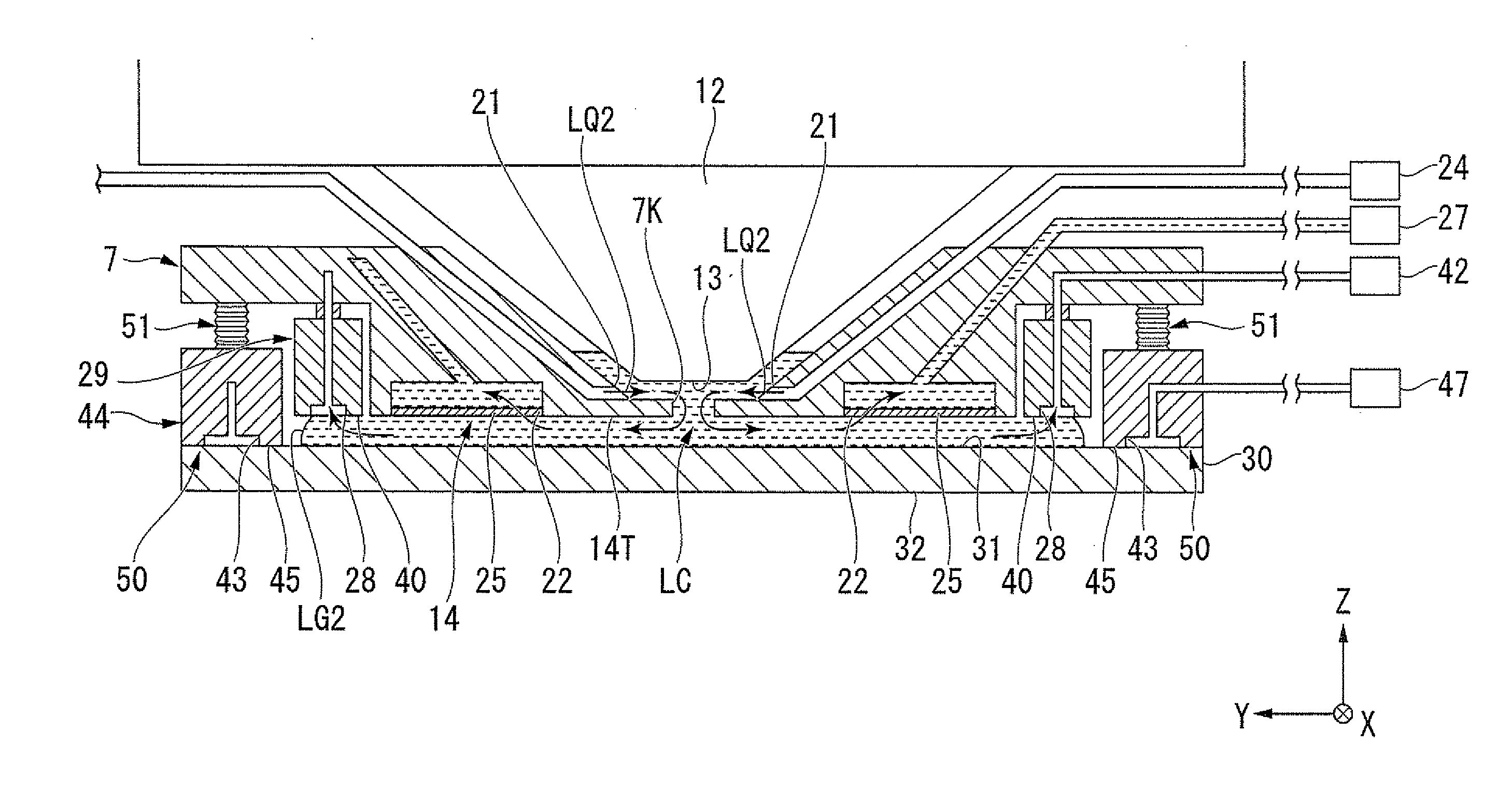
[0130]FIG. 11 is a view that shows one example of a cap member 30D according to the third embodiment. In FIG. 11, the cap member 30D is provided with supply ports 60, where through the second liquid LQ2 can be supplied. The supply ports 60 are disposed in at least part of an upper surface 31D of the cap member 30D, which is capable of opposing the lower surface 14. The supply ports 60 are capable of supplying the second liquid LQ2 to a space between the lower surface 14 and the upper surface 31D. In the present embodiment, in the state wherein the cap member 30D is held by the holding part 50, the supply ports 60 oppose the lower surface of the porous member 25. The supply ports 60 jet the second liquid LQ2 toward ...


PUM


Abstract

An exposure apparatus exposes a substrate with exposure light, which transits a first liquid. The exposure apparatus comprises: an optical member, which has an emergent surface wherefrom the exposure light emerges; a liquid immersion member, which at least partly surrounds an optical path of the exposure light emerging from the emergent surface, has a lower surface that the substrate opposes during an exposure of the substrate, and holds the first liquid between the substrate and at least part of the lower surface; and a plate member, which has a first surface and a second surface that faces the opposite direction to the first surface and which is capable of moving to a position at which it opposes the lower surface; wherein, cleaning is performed in a state wherein the first surface opposes the lower surface.

Description

CROSS-REFERENCE TO RELATED APPLICATION[0001]This application is a non-provisional application claiming priority to and the benefit of U.S. Provisional Application No. 61 / 365,862, filed Jul. 20, 2010, and is claiming priority to Japanese Patent Application No. 2009-237186, filed on Oct. 14, 2009. The entire contents of which are incorporated herein by reference.BACKGROUND[0002]1. Field of the Invention[0003]The present invention relates to an exposure apparatus, an exposing method, a maintenance method and a device fabricating method.[0004]2. Description of Related Art[0005]In the process of fabricating microdevices, such as semiconductor devices and electronic devices, using an immersion exposure apparatus that exposes a substrate with exposure light through a liquid is known, as disclosed in, for example, the patent literatures (U.S. Patent Application Publication No. 2005 / 0055575, U.S. Patent Application Publication No. 2008 / 0018867, U.S. Patent Application Publication No. 2004 / 02...

Claims


Application Information

Patent Timeline
Patent Type & Authority Applications(United States)
IPC IPC(8): G03B27/52
CPCG03F7/70925G03F7/70341G03F7/2041H01L21/0274
Inventor SATO, SHINJI
Owner NIKON CORP
Why Eureka
Try Eureka