Liquid immersion member, immersion exposure apparatus, liquid recovering method, device fabricating method, program, and storage medium

a technology of immersion exposure and immersion apparatus, which is applied in the field of liquid immersion member, immersion exposure apparatus, device fabricating method, program, etc., can solve the problems of exposure failure and defective device production, and achieve the effect of preventing defective devices from being produced, forming satisfactorily, and preventing exposure failures

Inactive Publication Date: 2012-01-19
NIKON CORP
View PDF4 Cites 10 Cited by
  • Summary
  • Abstract
  • Description
  • Claims
  • Application Information

AI Technical Summary

Benefits of technology

[0021]According to the aspects of the present invention, an immersion space can be formed satisfactorily. In addition, according to the aspects of the present invention, it is possible to prevent exposure failures from occurring and thereby to prevent defective devices from being produced.

Problems solved by technology

In the immersion exposure apparatus, exposure failures might occur if, for example, the immersion space cannot be formed in a desired state.
These problems could result in the production of defective devices.

Method used


Image

  • Liquid immersion member, immersion exposure apparatus, liquid recovering method, device fabricating method, program, and storage medium
  • Liquid immersion member, immersion exposure apparatus, liquid recovering method, device fabricating method, program, and storage medium
  • Liquid immersion member, immersion exposure apparatus, liquid recovering method, device fabricating method, program, and storage medium

Examples


first embodiment

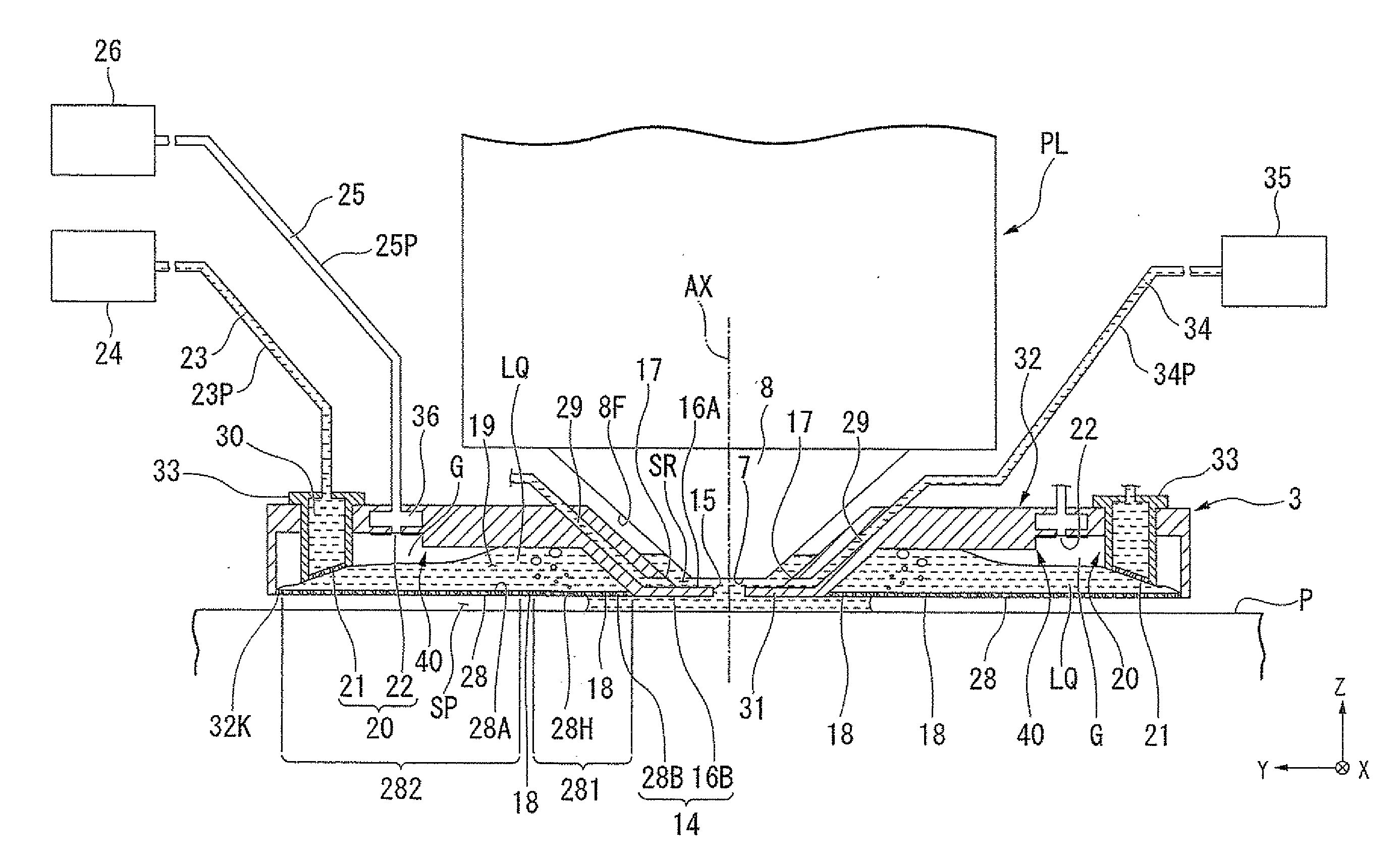
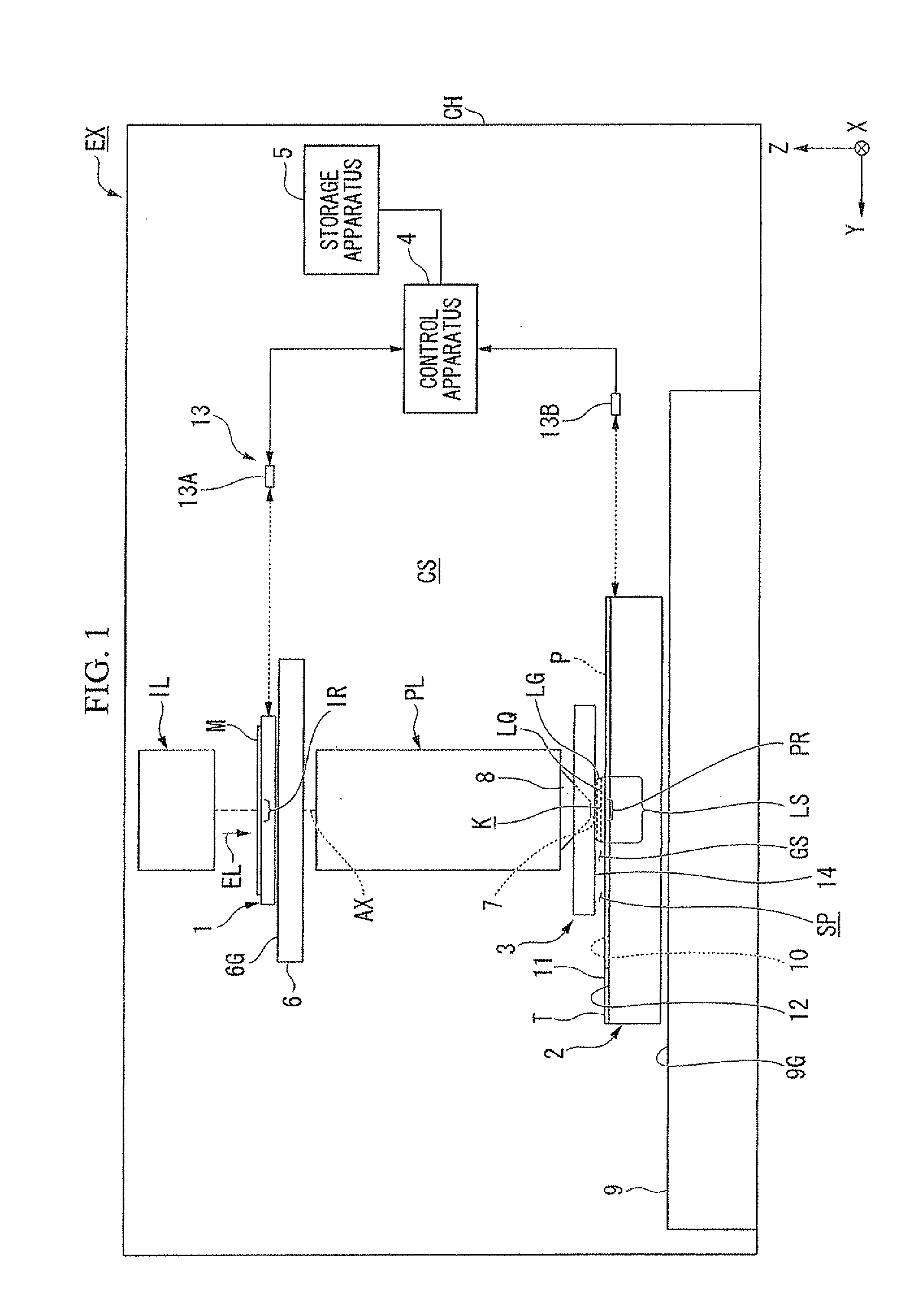
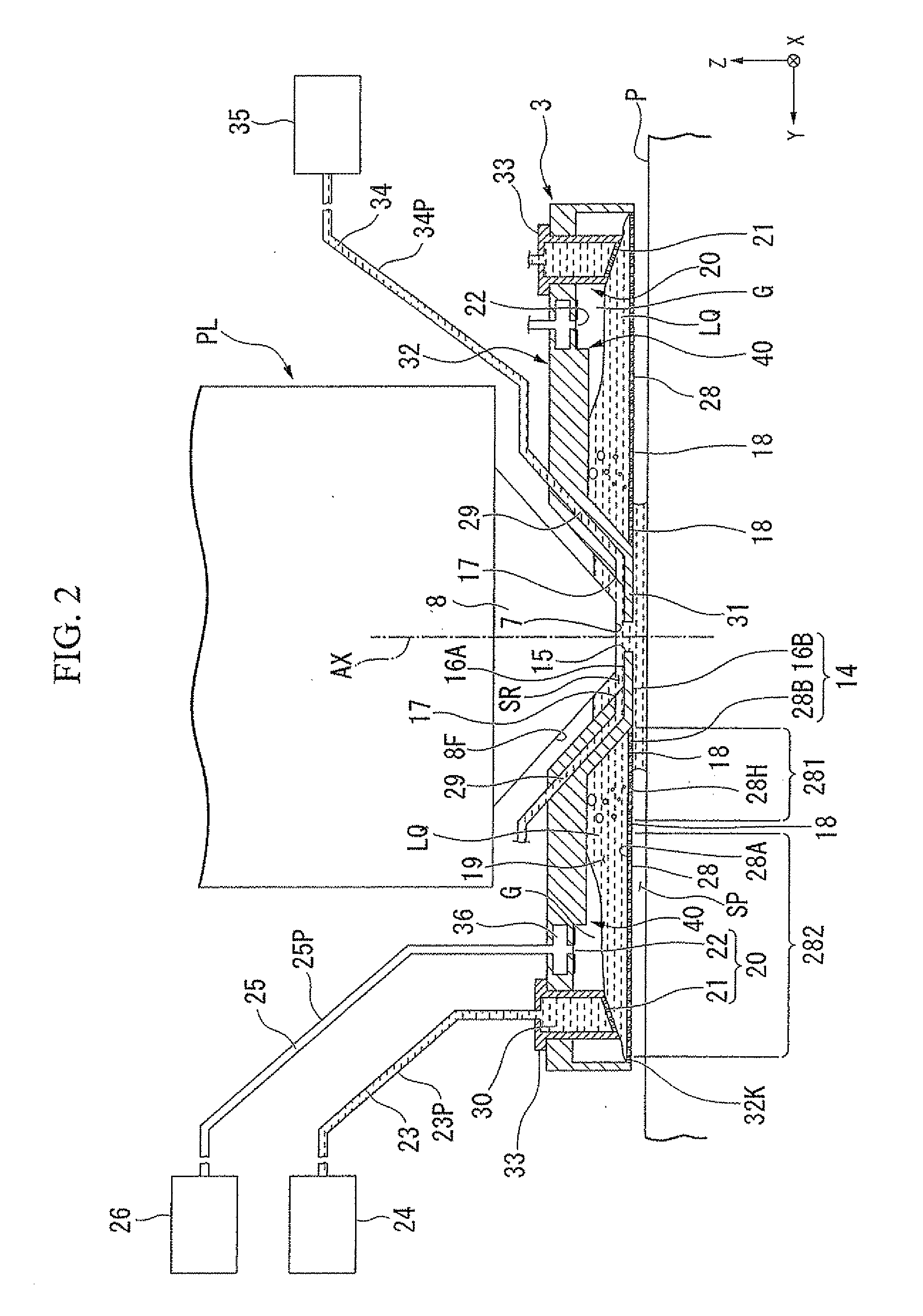
[0048]A first embodiment will now be explained. FIG. 1 is a schematic block diagram that shows one example of an exposure apparatus EX according to a first embodiment. The exposure apparatus EX of the present embodiment is an immersion exposure apparatus that exposes a substrate P with exposure light EL that passes through a liquid LQ. In the present embodiment, an immersion space LS is formed so that at least part of an optical path K of the exposure light EL is filled with the liquid LQ. An immersion space LS refers to a portion (i.e., a space or an area) that is filled with the liquid LQ. The substrate P is exposed with the exposure light EL, which transits the liquid LQ in the immersion space LS. In the present embodiment, water (i.e., pure water) is used as the liquid LQ.

[0049]In FIG. 1, the exposure apparatus EX comprises: a movable mask stage 1 that holds a mask M; a movable substrate stage 2 that holds the substrate P; an illumination system IL that illuminates the mask M wi...

second embodiment

[0200]A second embodiment will now be explained. In the explanation below, constituent parts that are identical or equivalent to those in the embodiment discussed above are assigned identical symbols, and the explanations thereof are therefore abbreviated or omitted.

[0201]FIGS. 10A and 10B include views that show one example of a second member 270 according to the second embodiment. The second member 270 comprises a third portion 2701 and a fourth portion 2702, which is disposed at a position higher than the third portion 2701 is and is capable of discharging a greater amount of the liquid LQ than the third portion 2701 is. In the second member 270, the spacing between adjacent holes 270H in the third portion 2701 is larger than the spacing between adjacent holes 270H in the fourth portion 2702. The percentage of the first discharge ports 21 (i.e., the holes 270H) per unit of area in a lower surface 270E is larger in the fourth portion 2702 than in the third portion 2701. In additio...

third embodiment

[0202]A third embodiment will now be explained. FIGS. 11A and 1113 include views that show one example of a second member 2720 according to the third embodiment. The second member 2720 comprises a third portion 2721 and a fourth portion 2722, which is disposed at a position higher than the third portion 2721 is and is capable of discharging a greater amount of the liquid LQ than the third portion 2721 is. In the second member 2720, the dimension of holes 272H in the fourth portion 2722 is larger than the dimension of the holes 272H in the third portion 2721. In the example shown in FIG. 11, the percentage of the first discharge ports 21 (i.e., the holes 272H) per unit of area in a lower surface 272B is larger in the fourth portion 2722 than in the third portion 2721.


PUM


Abstract

A liquid immersion member is disposed inside an immersion exposure apparatus and at least partly around an optical member and around an optical path of exposure light that passes through a liquid between the optical member and an object. The liquid immersion member comprising: a first member, which has a recovery port that recovers at least some of the liquid from a space above the object; a recovery passageway, wherein the liquid recovered via the recovery port flows; a second member, which faces the recovery passageway and has a first discharge port that is for discharging the liquid from the recovery passageway; and a third member, which faces the recovery passageway and has a second discharge port that is for discharging a gas from the recovery passageway. The second member comprises a first portion and a second portion, which is disposed at a position higher than the first portion is and is capable of discharging a greater amount of the liquid than the first portion is.

Description

CROSS-REFERENCE TO RELATED APPLICATION[0001]This application is a non-provisional application claiming priority to and the benefit of U.S. provisional application No. 61 / 364,101, filed Jul. 14, 2010. The entire contents of which are incorporated herein by reference.BACKGROUND[0002]1. Field of the Invention[0003]The present invention relates to a liquid immersion member, an immersion exposure apparatus, a liquid recovering method, a device fabricating method, a program, and a storage medium.[0004]2. Description of Related Art[0005]As disclosed in, for example, U.S. Patent Application Publication No. 2009 / 0046261, among exposure apparatuses used in photolithography, an immersion exposure apparatus is known that exposes a substrate with exposure light through a liquid in an immersion space.SUMMARY[0006]In the immersion exposure apparatus, exposure failures might occur if, for example, the immersion space cannot be formed in a desired state. These problems could result in the production...

Claims


Application Information

Patent Timeline
Patent Type & Authority Applications(United States)
IPC IPC(8): G03B27/52G03B27/42
CPCG03F7/709G03F7/70341G03F7/2041H01L21/0274
Inventor SATO, SHINJI
Owner NIKON CORP
Why Eureka
Try Eureka