Liquid immersion member, immersion exposure apparatus, liquid recovering method, device fabricating method, program, and storage medium

a technology of immersion exposure and immersion apparatus, which is applied in the field of liquid immersion member, immersion exposure apparatus, device fabricating method, program, etc., can solve the problems of exposure failure and defective device production, and achieve the effect of preventing defective devices from being produced, forming satisfactorily, and preventing exposure failures

Inactive Publication Date: 2012-01-19
NIKON CORP
View PDF3 Cites 7 Cited by
  • Summary
  • Abstract
  • Description
  • Claims
  • Application Information

AI Technical Summary

Benefits of technology

[0027]According to the aspects of the present invention, an immersion space can be formed satisfactorily. In addition, according to the aspects of the present invention, it is possible to prevent exposure failures from occurring and thereby to prevent defective devices from being produced.

Problems solved by technology

In the immersion exposure apparatus, exposure failures might occur if, for example, the immersion space cannot be formed in a desired state.
These problems could result in the production of defective devices.

Method used


Image

  • Liquid immersion member, immersion exposure apparatus, liquid recovering method, device fabricating method, program, and storage medium
  • Liquid immersion member, immersion exposure apparatus, liquid recovering method, device fabricating method, program, and storage medium
  • Liquid immersion member, immersion exposure apparatus, liquid recovering method, device fabricating method, program, and storage medium

Examples


first embodiment

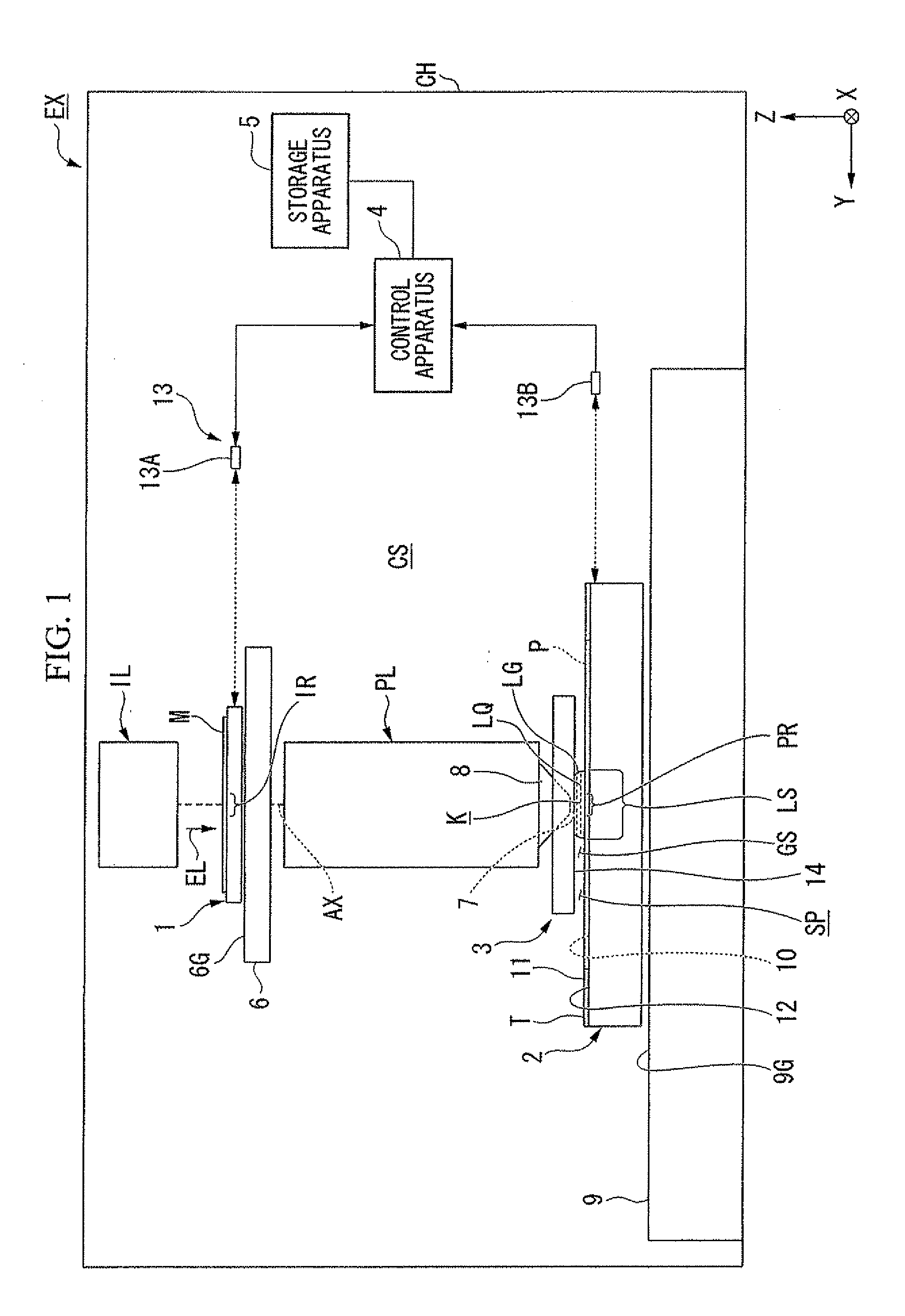
[0072]A first embodiment will now be explained. FIG. 1 is a schematic block diagram that shows one example of an exposure apparatus EX according to a first embodiment. The exposure apparatus EX of the present embodiment is an immersion exposure apparatus that exposes a substrate P with exposure light EL that passes through a liquid LQ. In the present embodiment, an immersion space LS is formed so that at least part of an optical path K of the exposure light EL is filled with the liquid LQ. An immersion space LS refers to a portion (i.e., a space or an area) that is filled with liquid LQ. The substrate P is exposed with the exposure light EL, which transits the liquid LQ in the immersion space LS. In the present embodiment, water (i.e., pure water) is used as the liquid LQ.

[0073]In FIG. 1, the exposure apparatus EX comprises: a movable mask stage 1 that holds a mask M; a movable substrate stage 2 that holds the substrate P; an illumination system IL that illuminates the mask M with t...

second embodiment

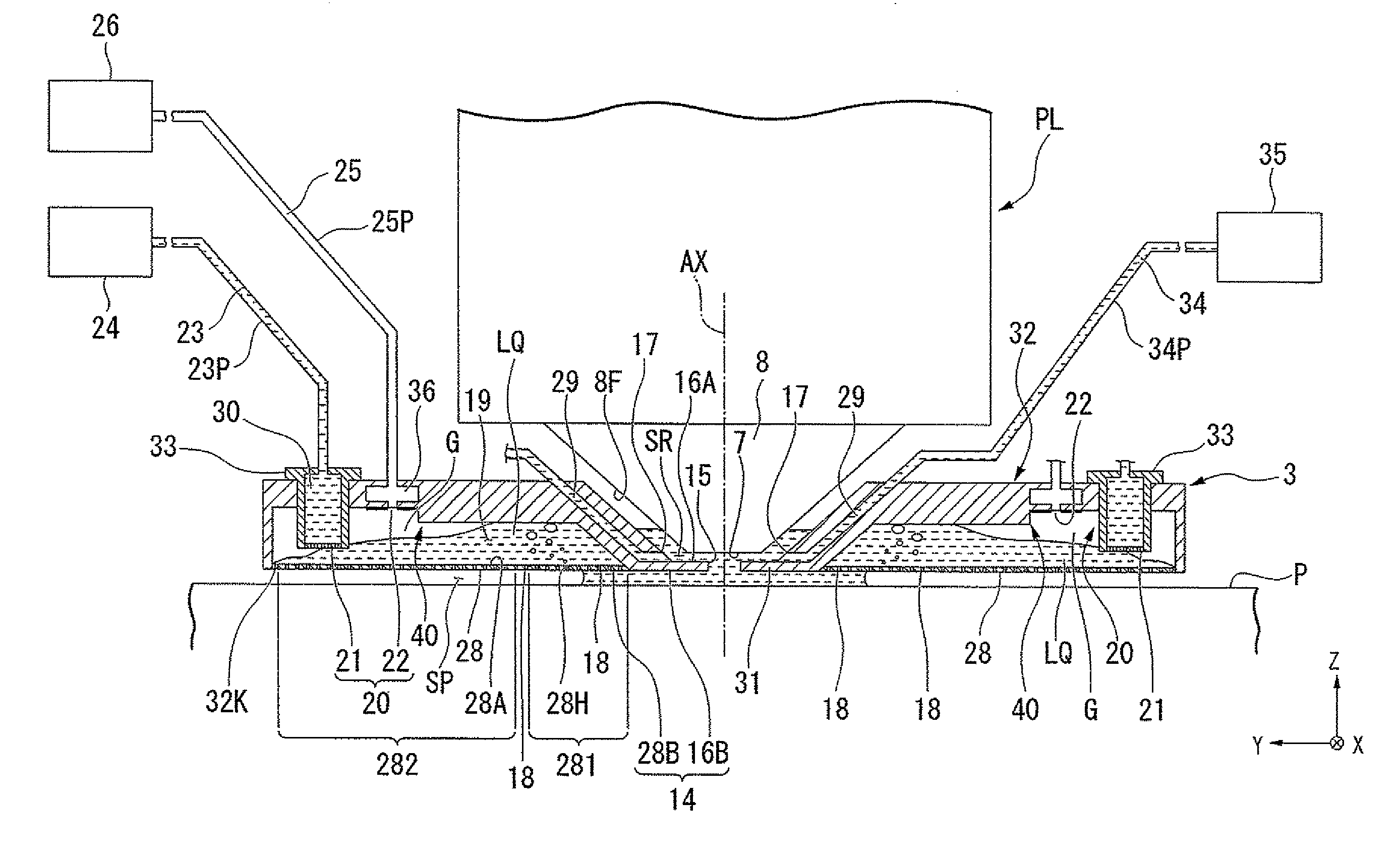
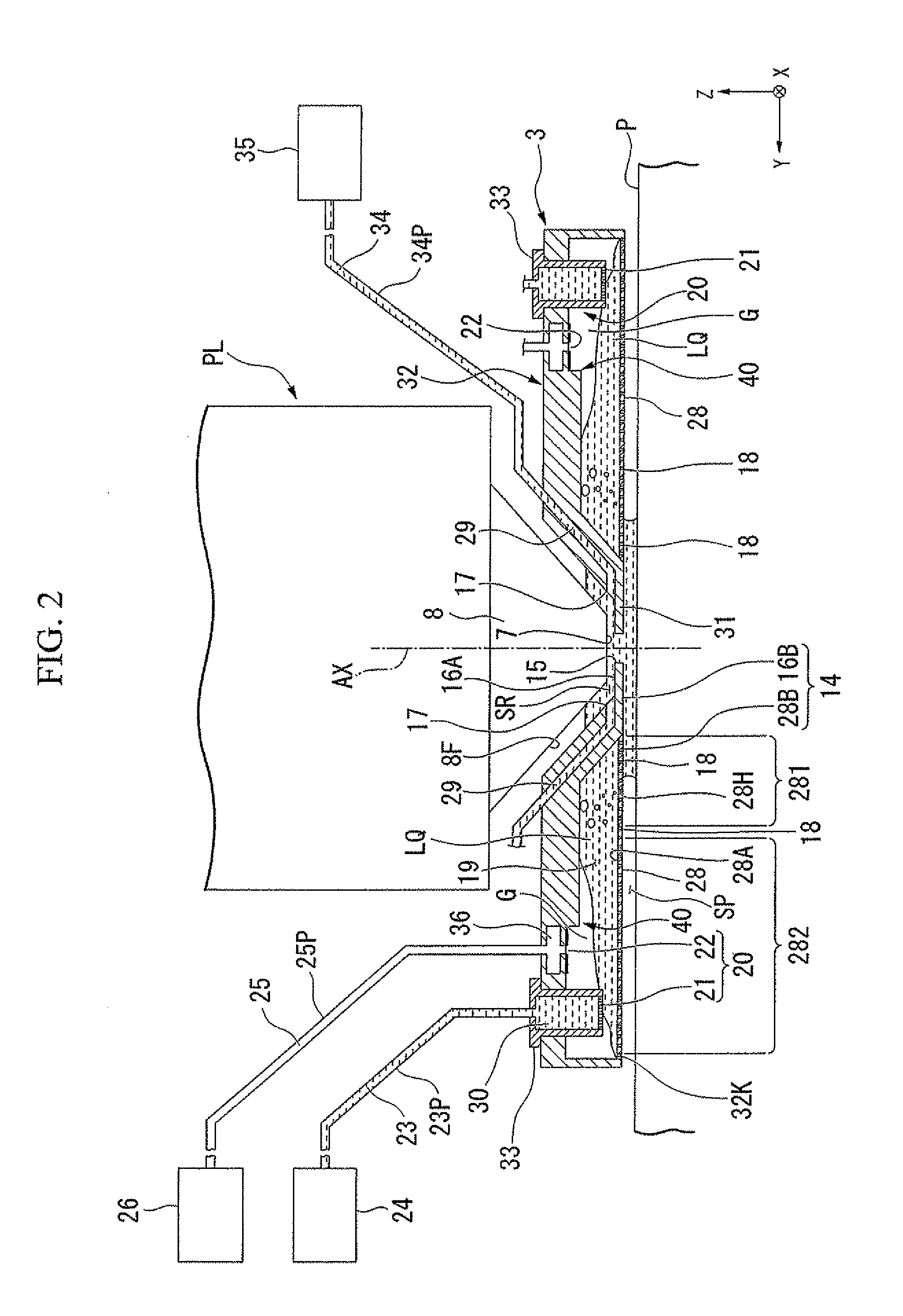
[0217]A second embodiment will now be explained. FIG. 9 is a view that shows one example of a liquid immersion member 308 according to the second embodiment. The liquid immersion member 308 comprises a hindering part 401, which hinders the liquid LQ in the recovery passageway 19 from contacting the second discharge ports 22. The hindering part 401 comprises a projection 411 and a liquid repellent part 421, which is disposed around the second discharge ports 22.

[0218]In the present embodiment, at least part of the surface of the projection 411 is liquid repellent with respect to the liquid LQ. The surface of the projection 411 includes a side surface 411S and a lower surface 411K. In the present embodiment, the lower surface 411K and the side surface 411S of the projection 411 are formed with the liquid repellent films Fr. Furthermore, just part of the side surface 411S (e.g., in the vicinity of the tip of the projection 411) may be formed with the liquid repellent film Fr. In additi...

third embodiment

[0221]A third embodiment will now be explained. FIG. 10 is a view that shows one example of a liquid immersion member 309 according to the third embodiment. The liquid immersion member 309 comprises a hindering part 402, which comprises a projection 412 and a liquid repellent part 422. The liquid repellent part 422 is disposed around the second discharge ports 22. The projection 412 is formed by a lower surface 412K and a side surface 412S.

[0222]In the present embodiment, the lower surface 412K, which extends from the tip (i.e., the lower end) of the projection 412 toward the optical path K, includes an inclined surface. In the present embodiment, at least part of the lower surface 412K is inclined upward toward the optical path K. In the present embodiment, the inclined lower surface 412K extends upward from the tip of the projection 412 toward the optical path K. In FIG. 10, the angle formed between the lower surface 412K and the side surface 412S is less than 90° (i.e., it is an ...


PUM


Abstract

A liquid immersion member is disposed inside an immersion exposure apparatus and at least partly around an optical member and an optical path of exposure light that passes through a liquid between the optical member and an object. The liquid immersion member comprises: a first member, which has a recovery port that recovers at least some of the liquid from the space above the object; a recovery passageway, wherethrough the liquid recovered via the recovery port flows; a discharge part, which has a first discharge port for discharging the liquid from the recovery passageway and a second discharge port for discharging a gas from the recovery passageway, that separately discharges the liquid and the gas from the recovery passageway; and a hindering part, which hinders the liquid in the recovery passageway from contacting the second discharge port.

Description

CROSS-REFERENCE TO RELATED APPLICATION[0001]This application is a non-provisional application claiming priority to and the benefit of U.S. provisional application No. 61 / 364,118, filed Jul. 14, 2010. The entire contents of which are incorporated herein by reference.BACKGROUND[0002]1. Field of the Invention[0003]The present invention relates to a liquid immersion member, an immersion exposure apparatus, a liquid recovering method, a device fabricating method, a program, and a storage medium.[0004]2. Description of Related Art[0005]As disclosed in, for example, U.S. Patent Application Publication No. 2009 / 0046261, among exposure apparatuses used in photolithography, an immersion exposure apparatus is known that exposes a substrate with exposure light through a liquid in an immersion space.SUMMARY[0006]In the immersion exposure apparatus, exposure failures might occur if, for example, the immersion space cannot be formed in a desired state. These problems could result in the production...

Claims


Application Information

Patent Timeline
Patent Type & Authority Applications(United States)
IPC IPC(8): G03B27/52
CPCG03F7/709G03F7/70341G03F7/2041H01L21/0274
Inventor SATO, SHINJI
Owner NIKON CORP
Why Eureka
Try Eureka