
Scroll compressor

a compressor and scroll technology, applied in the direction of machines/engines, rotary/oscillating piston pump components, liquid fuel engines, etc., can solve the problems of difficult to completely prevent the rotation degradation in performance, so as to prevent the orbiting scroll and stabilize the behavior of the orbiting scroll. , the effect of preventing the orbiting scroll

Active Publication Date: 2011-08-18
MITSUBISHI HEAVY IND LTD
View PDF6 Cites 14 Cited by
  • Summary
  • Abstract
  • Description
  • Claims
  • Application Information

AI Technical Summary

Benefits of technology

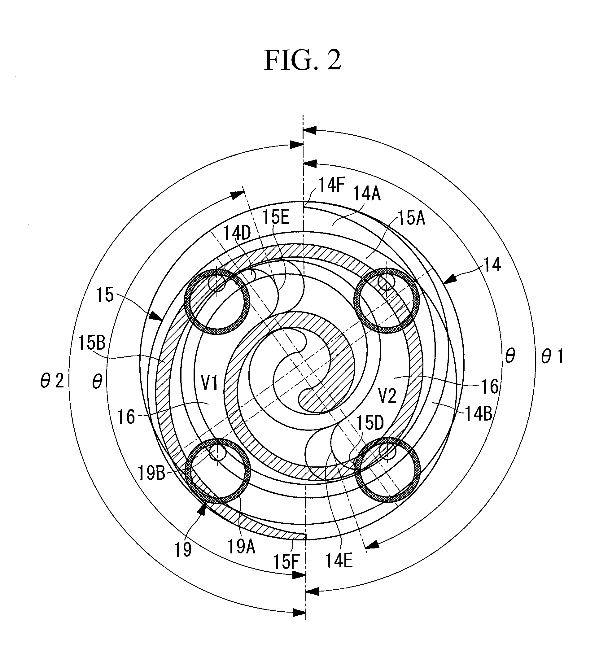
[0022]In the present invention, it is possible to prevent the orbiting scroll from rotating in a rocking (vibrating) manner by balancing a torsional moment in the orbital direction or the opposite direction caused by various forces and applied to the orbiting scroll depending on the operating conditions by a torsional moment in the direction opposite thereto caused by the pressure of the compression chamber having a larger volume, thereby stabilizing the behavior of the orbiting scroll. Accordingly, there is no need to set a gap larger than 0 (zero) to give a torsion between the spiral wraps of the scrolls in advance, and it is possible to prevent a reduction in the absolute value of the performance, the occurrence of abnormal noise due to impacts and the like, to improve and stabilize the performance, and to reduce operation noise.

Problems solved by technology

Accordingly, it is difficult to completely prevent rotation of the orbiting scroll with the rotation preventing mechanism.
As a result, the spiral wrap of the orbiting scroll periodically comes into contact with and is separated from the spiral wrap of the fixed scroll, causing degradation in performance due to gas leakage and abnormal noise due to impacts.

Method used


Image

  • Scroll compressor
  • Scroll compressor
  • Scroll compressor

Examples


first embodiment

[0028]A first embodiment of the present invention will be described below using FIGS. 1, 2, and 4.

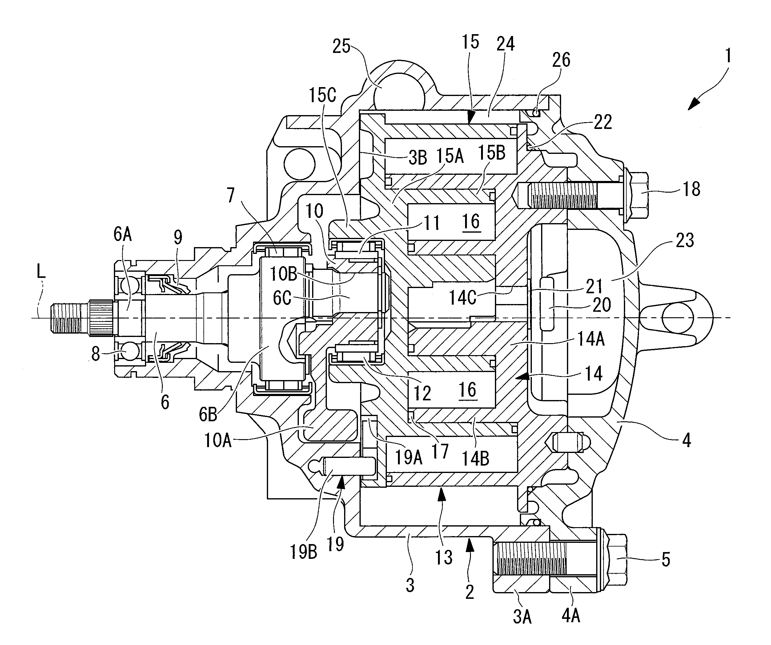
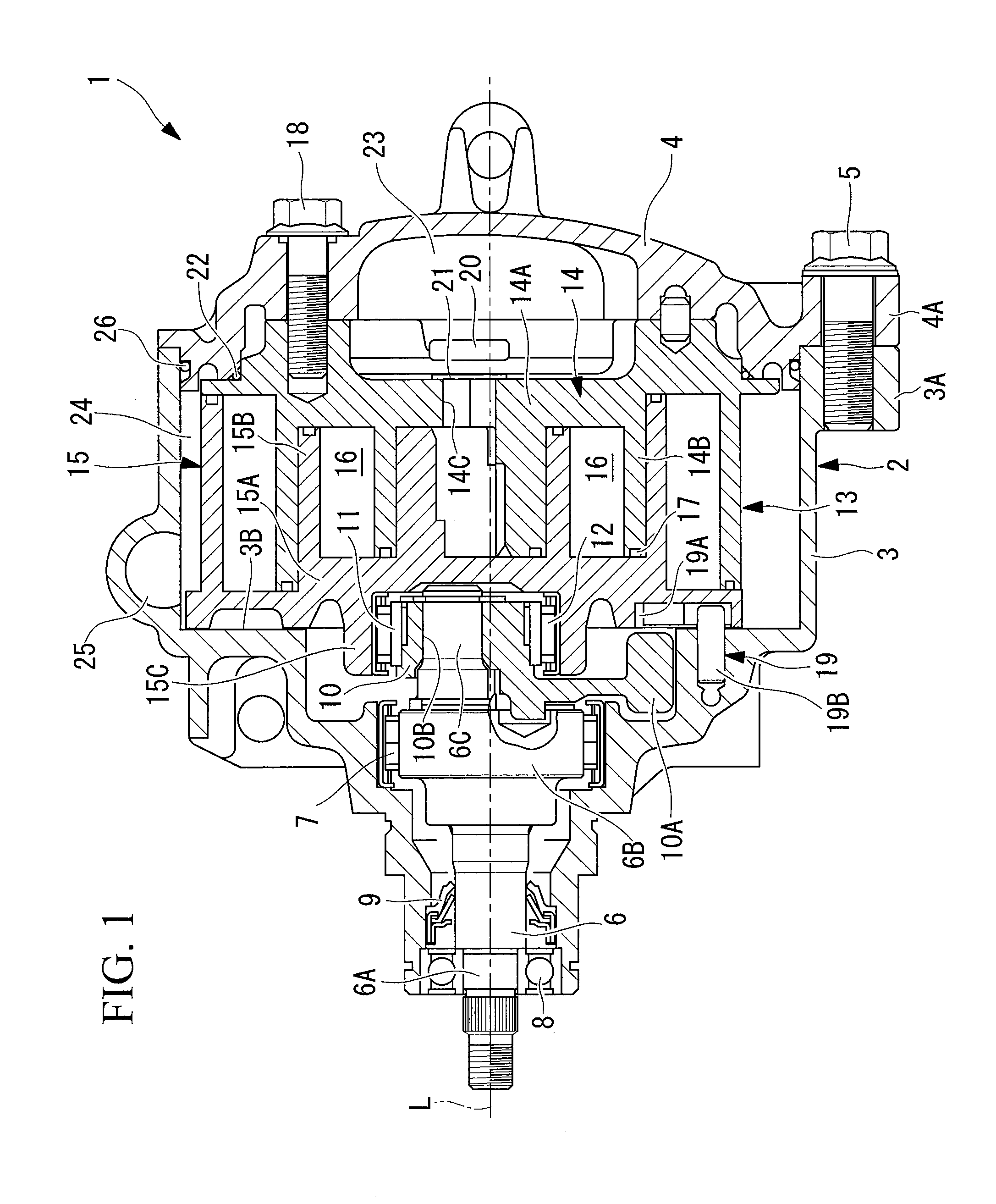
[0029]FIG. 1 shows a vertical cross-sectional view of a scroll compressor according to a first embodiment of the present invention. A scroll compressor 1 includes a housing 2 constituting an outer shell. The housing 2 is formed of a front housing 3 and a rear housing 4 that are securely fastened together with bolts 5. The front housing 3 and the rear housing 4 have fastening flanges 3A and 4A that are integrally formed at a plurality of, for example, four, positions on the circumference at regular intervals. By fastening together these flanges 3A and 4A with the bolts 5, the front housing 3 and the rear housing 4 are connected into a single component.

[0030]Inside the front housing 3, a crankshaft (drive shaft) 6 is supported so as to be rotatable about its axis L via a main bearing 7 and a sub-bearing 8. An end (the left side in FIG. 1) of the crankshaft 6 serves as a small-diameter sha...

second embodiment

[0057]Next, a second embodiment of the present invention will be described using FIGS. 3 and 4.

[0058]This embodiment is different from the above-described first embodiment in that the volumes V1 and V2 of a pair of compression chambers 16 are differentiated by changing the height in the axial direction of the spiral wraps on the outer circumferential side. Since the other points are the same as the first embodiment, the descriptions thereof will be omitted.

[0059]In this embodiment, as shown in FIG. 3, the volume V1 of the compression chamber 16 formed on the ventral-surface side of the fixed spiral wrap 14B and the volume V2 of the compression chamber 16 formed on the ventral-surface side of the orbiting spiral wrap 15B are differentiated by making the spiral wraps 14B and 15B on the outer circumferential end side of the step portions 14E and 15E of the fixed scroll 14 and the orbiting scroll 15 have different heights in the axial direction.

[0060]That is, assuming that the dimension...


PUM


Abstract

An object is to provide a scroll compressor capable of preventing degradation in performance and the occurrence of abnormal noise due to a torsional moment applied to an orbiting scroll, by utilizing the structural advantages of so-called stepped scroll compressors. In a so-called stepped scroll compressor (1), in a pair of compression chambers (16) arranged in a point-symmetrical configuration among a plurality of compression chambers (16), the volume V1 of the compression chamber (16) formed on the ventral-surface side of the fixed spiral wrap (14B) of the fixed scroll (14) when intake is cut off and the volume V2 of the compression chamber (16) formed on the ventral-surface side of the orbiting spiral wrap (15B) of the orbiting scroll (15) are different from each other.

Description

TECHNICAL FIELD[0001]The present invention relates to a so-called stepped scroll compressor, in which a pair of a fixed scroll and an orbiting scroll forming compression chambers have step portions provided in the spiral direction.BACKGROUND ART[0002]Conventionally, a scroll compressor in which each of a fixed scroll and an orbiting scroll has step portions provided at arbitrary positions in the spiral direction of the top surfaces and bottom surfaces of spiral wraps, and in which the spiral wraps having a higher wrap height on the outer circumferential side with respect to the step portions than on the inner circumferential side is known (for example, see PTL 1). Since the height of the compression chambers in the axial direction is higher on the outer circumferential side than on the inner circumferential side of the spiral wraps, this scroll compressor constitutes a scroll compressor capable of three-dimensional compression, i.e., compressing gas both in the circumferential direc...

Claims


Application Information

Patent Timeline
Patent Type & Authority Applications(United States)
IPC IPC(8): F01C1/02
CPCF01C17/063F04C2270/13F04C18/0276F04C18/0215F04C18/02F04C29/06
Inventor HIRATA, HIROHUMIUKAI, TETSUZOYAMAZAKI, HIROSHIITO, TAKAHIDE
Owner MITSUBISHI HEAVY IND LTD
Learn More