Force plate with spring elements

a technology of force plate and spring element, applied in the field of force plate, can solve the problems of relatively complex force plate, difficult production, and rods provided, and achieve the effect of reducing or avoiding cross-talk and less complex production

Inactive Publication Date: 2011-09-01
SARTORIUS LAB INSTR GMBH & CO KG
View PDF20 Cites 4 Cited by
  • Summary
  • Abstract
  • Description
  • Claims
  • Application Information

AI Technical Summary

Benefits of technology

[0006]It is therefore an object of the present invention to improve the known force plate so as to make the design and thus the production less complex and more economical. A further object is to reduce or avoid cross-talk between the vertically and horizontally conducted forces.

Problems solved by technology

A disadvantage of the known force plate is that further horizontal bending webs or bending rods are provided above and below, arranged parallel to the horizontally arranged spring element that is provided with strain gauges.
This results in a force plate which is relatively complex and therefore difficult to produce.

Method used


Image

  • Force plate with spring elements
  • Force plate with spring elements
  • Force plate with spring elements

Examples


Embodiment Construction

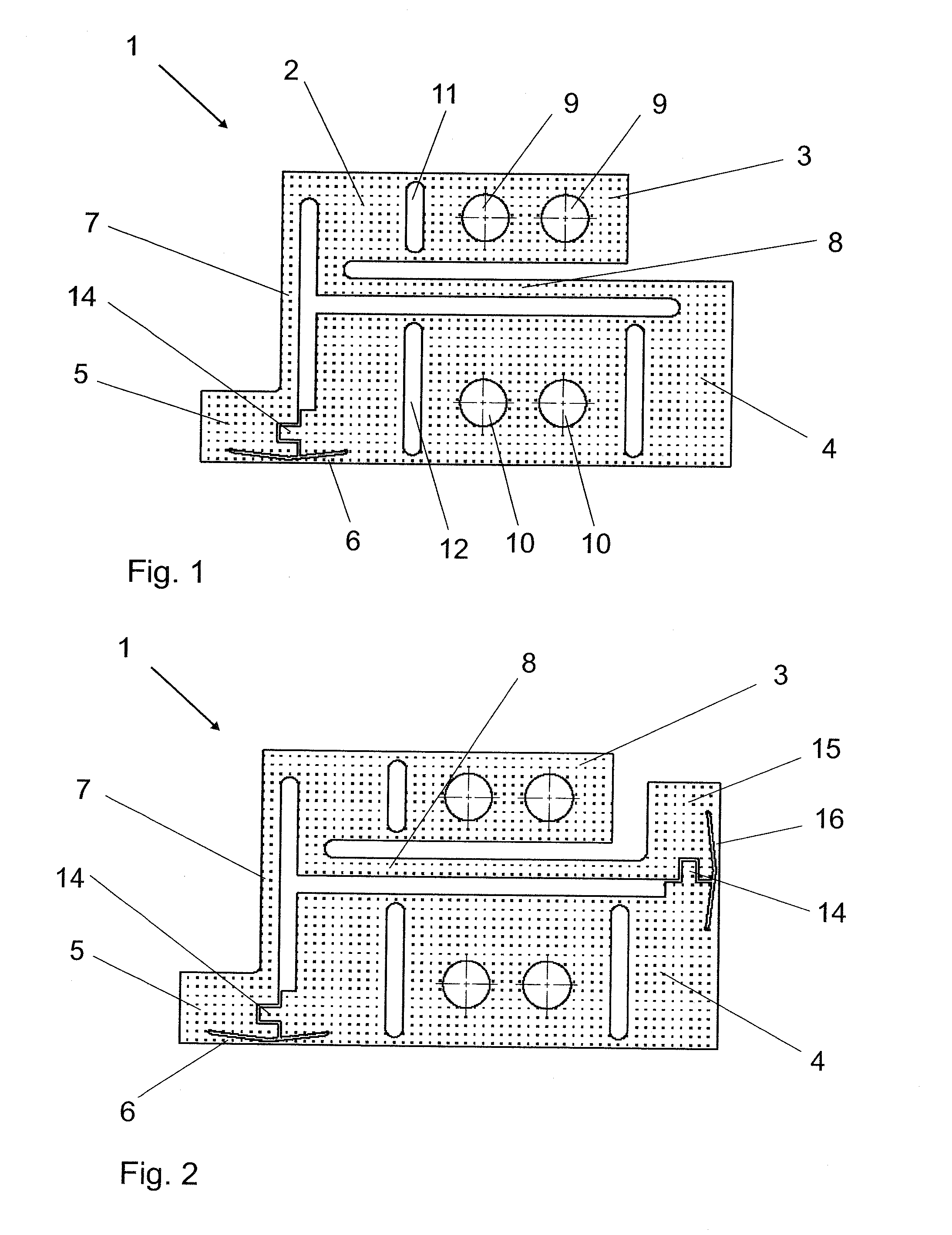
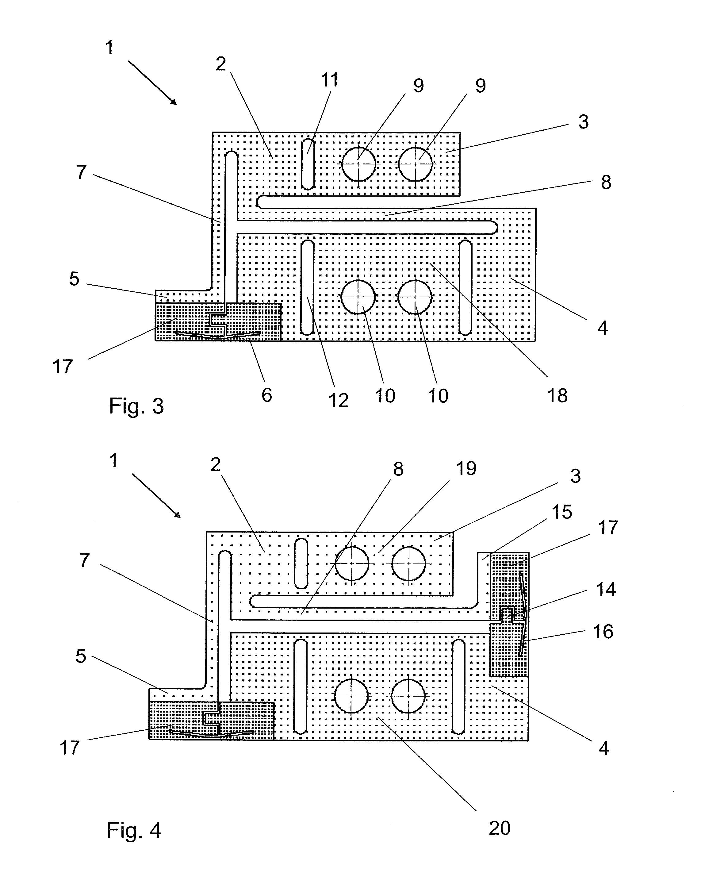
[0033]A force plate 1 includes a plate-shaped carrier 2 with an upper carrier section 3, a lower carrier section 4, a first end carrier section 5 and a horizontal spring element 6.

[0034]The plate-shaped carrier 2 comprises, at the top in the vertical direction, the upper carrier section 3 which is connected by a vertical rod 7 to the first end carrier section 5 which is positioned in front of the lower carrier section 4. The first end carrier section 5 is, in turn, connected via the horizontally arranged spring element 6 to the lower carrier section 4 which is arranged parallel to the upper carrier section 3. At the end facing away from the first end carrier section 5, the lower carrier section 4 is connected by a horizontal rod 8 to the end of the upper carrier section 3 facing toward the vertical rod 7.

[0035]The plate-shaped carrier 2 is configured to be fastened with its upper carrier section 3 via two holes 9 and with its lower carrier section 4 via two holes 10. The vertical sl...


PUM

PropertyMeasurementUnit
forceaaaaaaaaaa
thicknessaaaaaaaaaa
widthaaaaaaaaaa

Abstract

Force plate (1) having a plate-shaped carrier (2) which, when arranged vertically, has an upper carrier section (3) at the top in the vertical direction and a lower carrier section (4) at the bottom in the vertical direction. A first end carrier section (5) is connected, on the one hand, to the upper carrier section (3) via a vertical rod (7) and, on the other hand, to the lower carrier section (4) via a horizontally oriented spring element (6). That end of the lower carrier section (4) which faces away from the first end carrier section (5) is connected to the upper carrier section (3) via a horizontal rod (8). A second end carrier section (15) connects the horizontal rod (8) to the lower carrier section (4) via a vertically arranged spring element (16).

Description

[0001]This is a Continuation of International Application PCT / EP2009 / 007736, with an international filing date of Oct. 29, 2009, which was published under PCT Article 21(2) in German, and claims priority to German Patent Application No. 10 2008 056 715.9, with a filing date of Nov. 11, 2008, the entire disclosures of which are incorporated into this application by reference.FIELD AND BACKGROUND OF THE INVENTION[0002]The present invention relates to a force plate comprising a plate-shaped carrier which, when arranged vertically, has an upper carrier section at the top in the vertical direction and a lower carrier section at the bottom in the vertical direction, wherein at least one first end carrier section is provided and is connected, at one side, to the upper carrier section via a vertical rod and, at another side, to the lower carrier section via a horizontally arranged spring element that is provided with strain gauges.[0003]DE 28 13 769 A1, which corresponds to U.S. Pat. No. 4,...

Claims


Application Information

Patent Timeline
Patent Type & Authority Applications(United States)
IPC IPC(8): G01L1/22G01G3/14
CPCG01G3/1414G01L1/044G01G23/002
Inventor KUHLMANN, OTTOMUECK, TANJARELLING, VOLKERPETZOLD, GERALD
Owner SARTORIUS LAB INSTR GMBH & CO KG
Why Eureka
Try Eureka