Rotary energy converter with retractable barrier

a technology of rotary energy converter and barrier, which is applied in the direction of liquid fuel engines, machines/engines, rotary piston liquid engines, etc., can solve the problems of less desirable ‘idling’, achieve compact and efficient operation, reduce starting energy, and operate with little or no additional cooling

Active Publication Date: 2012-10-16
HUDSON SCOTT
View PDF34 Cites 4 Cited by
  • Summary
  • Abstract
  • Description
  • Claims
  • Application Information

AI Technical Summary

Benefits of technology

[0007]The presently disclosed rotary internal combustion engine, energy converter and method of combusting offer numerous advantages in the art. For example, the presently disclosed device is compact and efficient, and is adapted to perform multiple energy functions including harnessing energy, storing energy, and recovering energy, and requires reduced starting energy thereby making ‘idling’ less desirable. The device also operates at lower temperatures than many conventional engines and may be operated with little or no additional cooling. The lower operating temperatures also may allow for pre-heating of a combustible fluid without pre-ignition, the use of lower quality fuels and the production of fewer pollutants than many conventional internal combustion engines. Additionally, the device may include lighter weight components than many conventional engines and operates with reduced back pressure, reduced exhaust noise, reduced (if not eliminated) starting energy and less vibration as compared to other engines. The device also benefits from increased intake and exhaust volumetric efficiency. The device is also adapted to create a thrust stream. The thrust stream can be harnessed under atmospheric conditions, as well as when atmospheric intake is not available. Since compression is not necessary, lower octane fuels can be used. Also, since the combustion chamber is expanding before combustion, fuel vaporization is improved, including the vaporization of hard to vaporize fuels. Advantageously, the vaporization also increases fuel efficiency, and cools the input charge and the engine. The expansion before combustion also advantageously provides the reduced pressure of a carburetor without a separate carburetor and without the intake drag of a venturi-inducing flow restriction to the intake. Similarly, the expansion before combustion may eliminate the need for a separate, high pressure fuel injector.

Problems solved by technology

For example, the presently disclosed device is compact and efficient, and is adapted to perform multiple energy functions including harnessing energy, storing energy, and recovering energy, and requires reduced starting energy thereby making ‘idling’ less desirable.

Method used


Image

  • Rotary energy converter with retractable barrier
  • Rotary energy converter with retractable barrier
  • Rotary energy converter with retractable barrier

Examples


Embodiment Construction

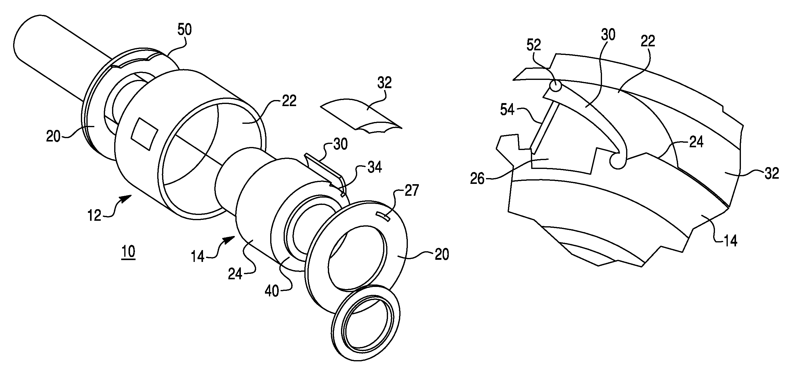
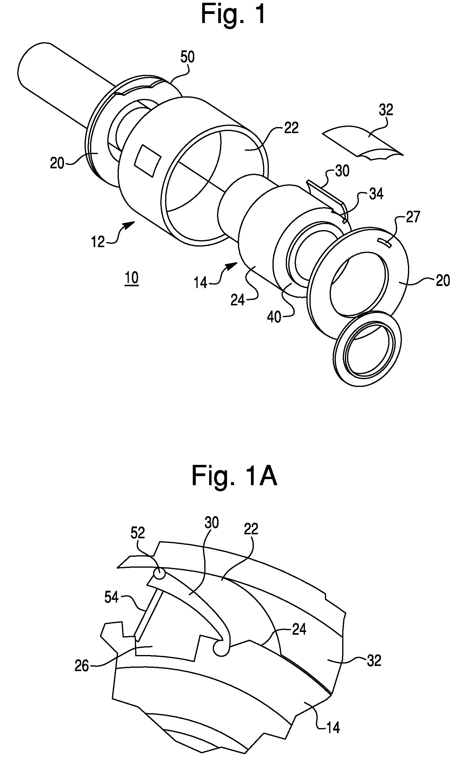
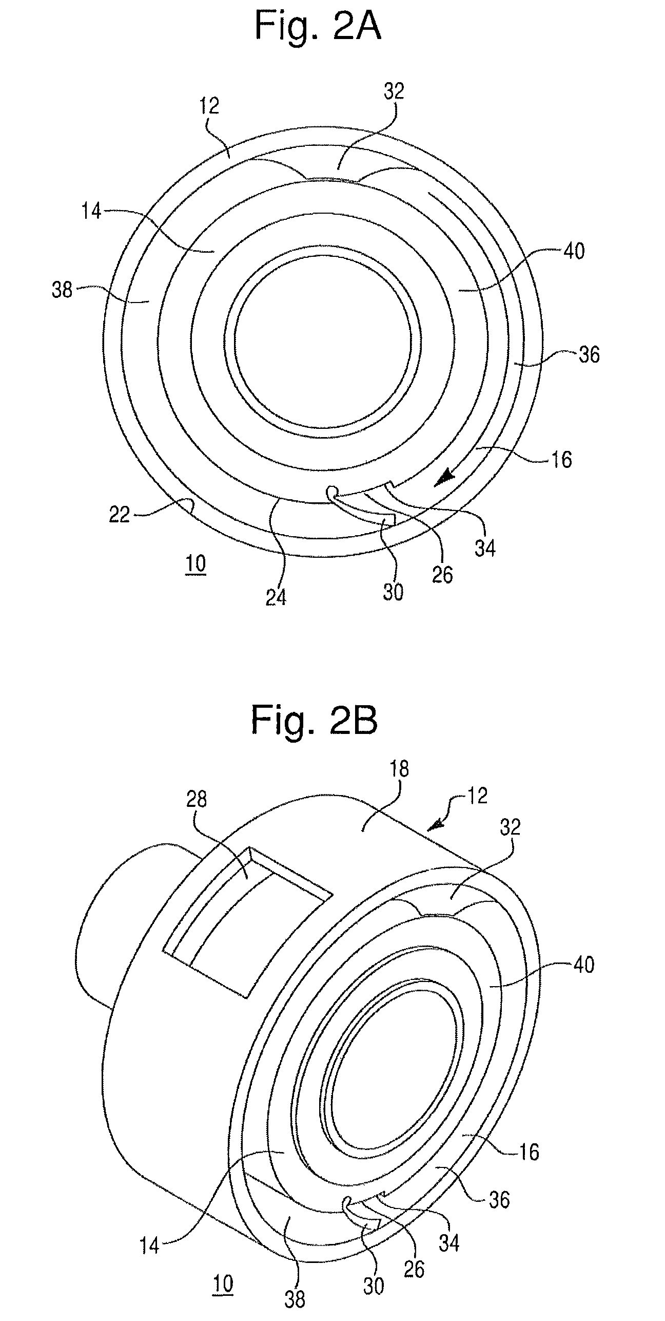
[0020]Rotary energy converters according to the present disclosure may be variously configured. In many embodiments, rotary energy converters may comprise a rotary internal combustion engine 10 including an outer housing 12 and an inner housing 14 centrally disposed within the outer housing 12. A hollow enclosure 16 may be defined between an inner peripheral surface of the outer housing 22 and an outer peripheral surface of the inner housing 24. The housings may have a variety of configurations and in many embodiments the outer and inner housings are cylindrical. However, one or both housings may not be cylindrical, for example the outer or inner housing may comprise an ellipse or parabola or be irregularly shaped, so long as they define an enclosure between their inner and outer surfaces, respectively. Additionally, the enclosure defined between the outer and inner housings may have a variety of cross-sections. For example, in the illustrated embodiments the rotary engine includes ...


PUM


Abstract

A rotary internal combustion engine includes an outer housing and an inner housing and an enclosure defined therebetween. At least one of the outer and inner housings is rotatable relative to the other and at least two barriers are disposed in the enclosure and divide the enclosure into a combustion chamber and an exhaust chamber. At least one barrier is rotatable relative to at least one other barrier and at least one barrier comprises a retractable barrier mounted along a pivot axis and is pivotable between an extended position and a retracted position. An intake port, exhaust port, and ignition source are also provided. A method of combusting a fuel comprises rotating a drive member to expand a combustion chamber and substantially isolate the combustion chamber from an exhaust chamber, and introducing and combusting a combustion fluid and a fuel in the combustion chamber as the combustion chamber is expanding.

Description

FIELD OF THE INVENTION[0001]The present disclosure relates to energy producing and transferring devices and in particular, to internal combustion rotary engines and rotary energy converters.BACKGROUND OF THE INVENTION[0002]Internal combustion engines perform useful work by combusting a fuel and producing expanding hot gases that act directly on and thereby move parts of the engine. Typically, the steps involved in internal combustion include 1) the intake of a vaporized fuel and an oxidizer (typically air); 2) the compression of the oxidizer; 3) the ignition of the vaporized fuel and oxidizer; 4) the combustion of the fuel and the expansion of the resulting gases which act on the engine part; and 5) the exhaust of the combustion gases. A variety of types of internal combustion engines exist, including, for example, reciprocating or piston engines, rotary engines, and turbines. However, existing engines suffer from a number of drawbacks. For example, conventional engines typically in...

Claims


Application Information

Patent Timeline
Patent Type & Authority Patents(United States)
IPC IPC(8): F02B53/00F02B53/04F01C1/00F04C18/00F04C2/00
CPCF01C1/321F01C1/322F01C1/40F01C21/0809F02B55/00F02B53/00F01C21/104F04C2250/102Y02T10/17Y02T10/12F02B53/10F02B53/12F02B55/14
Inventor HUDSON, SCOTT
Owner HUDSON SCOTT
Why Eureka
Try Eureka