Device for turning up the tire sidewalls on a tire building drum

a technology of sidewalls and tire building drums, which is applied in the direction of tires, domestic applications, other domestic articles, etc., can solve the problems of high wear of side shaping bellows, the need for manual finishing operation, and the need for corresponding replacement, so as to achieve less production waste, increase connection quality, and high connection quality

Inactive Publication Date: 2006-12-05
CONTINENTAL REIFEN DEUTSCHLAND GMBH
View PDF14 Cites 3 Cited by
  • Summary
  • Abstract
  • Description
  • Claims
  • Application Information

AI Technical Summary

Benefits of technology

[0010]One advantage of the invention can be seen in particular in that through the device according to the invention the two opposite lever systems, which are connected to the lever supporting body in a pivoted manner, spread apart simultaneously and thus turn up the two tire sidewalls on both sides of the carcass in a synchronous and continuous manner. The simultaneous turning up of the tire sidewalls causes the material layers to be pressed against the shaped carcass respectively with the same contact pressure, through which a high connection quality between the material layers is achieved. The use of the spindles further causes a continuously constant movement of the lever system, which contributes to an increase in connection quality and thus leads to less production wastage.
[0011]In an advantageous embodiment of the invention a hollow spindle with two movable core stretching devices is arranged in a coaxial manner around the base spindle. The hollow spindle is provided for the axial movement of the core stretching devices. When embodied as a hollow spindle, it has the advantage, e.g., that it is integrated in the tire building drum in a space-saving manner.
[0012]In a further advantageous embodiment of the invention the rotation of the hollow spindle can be coupled to the rotation of the base spindle via a coupling. The coupling has the advantage that the base spindle simultaneously drives the hollow spindle via the coupling and thus a separate drive of the hollow spindle can be omitted.
[0013]In a further advantageous embodiment of the invention the rotation of the hollow spindle can be decoupled from the rotation of the base spindle via the coupling. When spreading apart the lever system only the lever supporting bodies should move further towards one another, whereas the two core stretching devices in contrast should remain stationary. The separation of the rotation of the hollow spindle from the rotation of the base spindle is advantageously achieved via the coupling.
[0014]In a further advantageous embodiment of the invention the hollow spindle is supported on the base spindle via at least one ball bearing. The ball bearing minimizes the frictional effects as soon as the coupling is uncoupled and only the base spindle continues to rotate.
[0015]In another advantageous embodiment of the invention the rotation of the hollow spindle can be stopped via a braking device. The braking device blocks the rotation of the hollow spindle completely and thus ensures that the core stretching devices can no longer move.

Problems solved by technology

The turning up process with the aid of side shaping bellows can have the disadvantage that these bellows do not act all the way up to the shoulder areas of the green tire, making manual finishing operation necessary.
Furthermore, the side shaping bellows are subject to a high wear, making necessary a correspondingly frequent replacement, which is associated with a high expenditure of time.
A major disadvantage with this principle is that, e.g., due to different frictional effects, the spreading apart of the opposite tire lever systems does not always occur simultaneously or suddenly.
The consequence of the two roller lever systems being spread apart at different times is that the sidewalls are not pressed uniformly against the shaped carcass and a defective connection between the two material layers thus occurs, which in turn can lead to tire wastage.

Method used


Image

  • Device for turning up the tire sidewalls on a tire building drum
  • Device for turning up the tire sidewalls on a tire building drum

Examples


Embodiment Construction

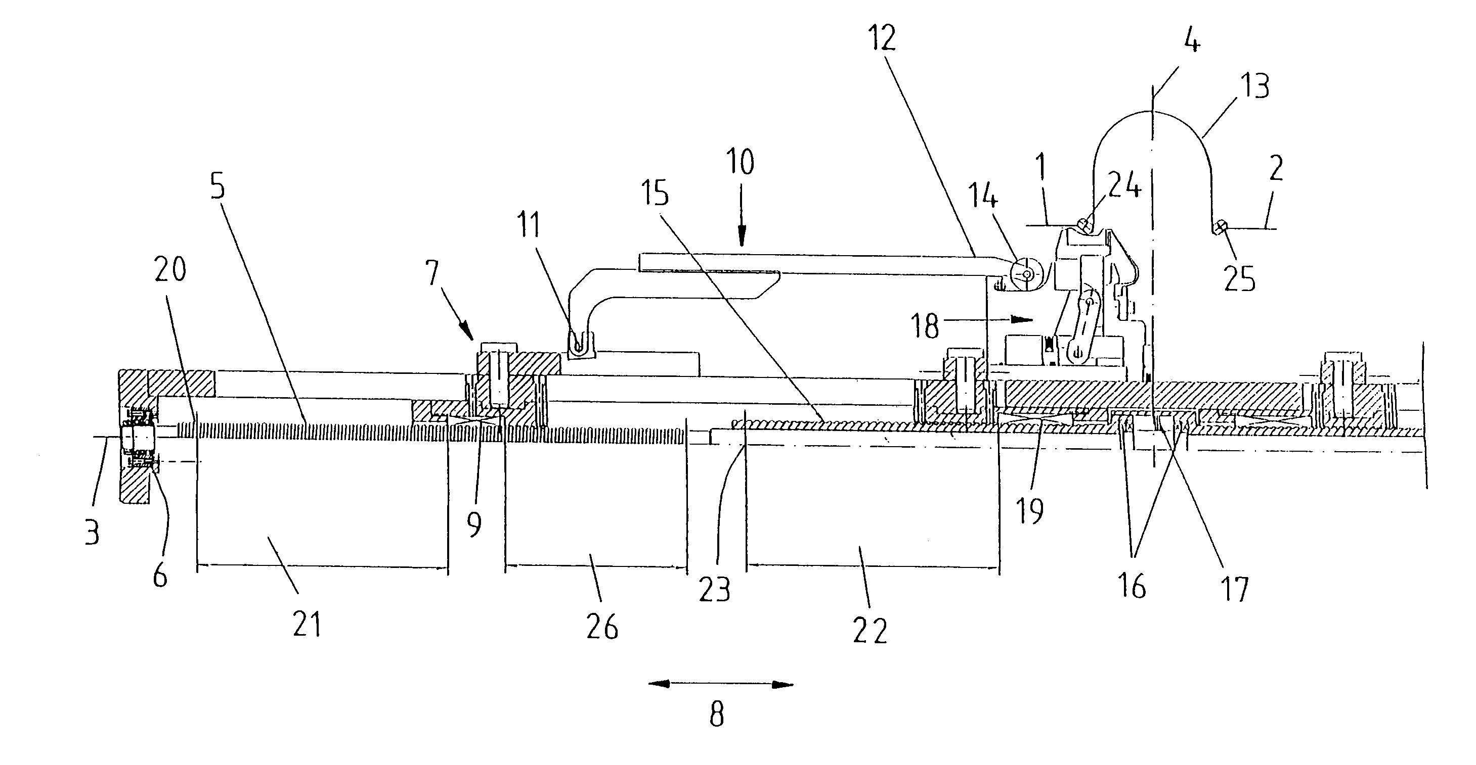
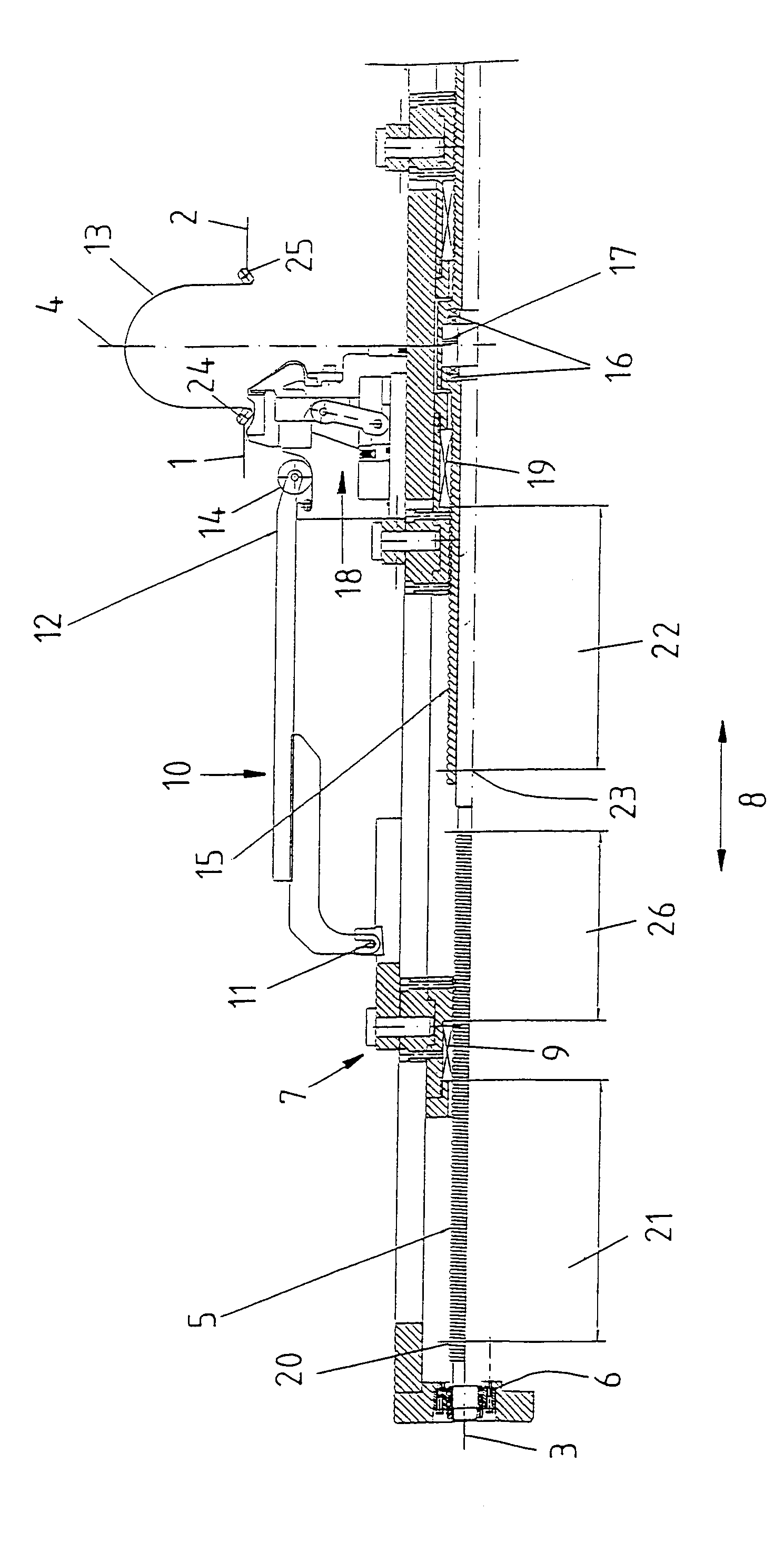
[0045]The particulars shown herein are by way of example and for purposes of illustrative discussion of the embodiments of the present invention only and are presented in the cause of providing what is believed to be the most useful and readily understood description of the principles and conceptual aspects of the present invention. In this regard, no attempt is made to show structural details of the present invention in more detail than is necessary for the fundamental understanding of the present invention, the description taken with the drawings making apparent to those skilled in the art how the several forms of the present invention may be embodied in practice.

[0046]The tire building drum is installed essentially in an axial symmetrical manner relative to a drum axis 3 and to a drum center 4. Thus, the invention is shown in partial form. Moreover, because the respectively opposite components are generally identical, they are not shown in the FIGURE. A base spindle 5 is mounted ...


PUM

PropertyMeasurementUnit
rotationaaaaaaaaaa
axial movementaaaaaaaaaa
areaaaaaaaaaaa

Abstract

Device for turning up sidewalls of a tire. The device includes a first lever supporting body arranged on a first side of a drum center and being movable in an axial direction. A first lever system pivotally connected to the first lever supporting body. A second lever supporting body arranged on a second side of the drum center and being movable in an axial direction. A second lever system pivotally connected to the second lever supporting body. The first and second sides are arranged on opposite sides of the drum center. A base spindle is adapted to move the first and second lever supporting bodies in an axial synchronous manner relative to each another.

Description

CROSS-REFERENCE TO RELATED APPLICATIONS[0001]The present application claims priority under 35 U.S.C. §119 of German Patent Application No. 103 00 969.8, filed on Jan. 14, 2003, the disclosure of which is expressly incorporated by reference herein in its entirety.BACKGROUND OF THE INVENTION[0002]1. Field of the Invention[0003]The invention relates to a device for turning up the tire sidewalls on a tire building drum with devices for shaping a tire carcass, whereby the tire building drum features two lever systems arranged essentially and / or generally symmetrically to the drum center, which lever systems are each connected to a lever supporting body in a pivoted manner, whereby the two lever supporting bodies can be moved in the axial direction of the tire building drum.[0004]2. Discussion of Background Information[0005]In the conventional production of new tires, one production step takes place on a tire building drum, in which the tire carcass at first resting flat is shaped by an e...

Claims


Application Information

Patent Timeline
Patent Type & Authority Patents(United States)
IPC IPC(8): B29D30/24B29D30/32B29D30/72
CPCB29D30/244B29D30/32B29D2030/3264
Inventor JUNGK, ANDREAS
Owner CONTINENTAL REIFEN DEUTSCHLAND GMBH
Why Eureka
Try Eureka