Sensory structure of capacitive touch panel and capacitive touch panel having the same

a capacitive touch panel and sensor technology, applied in the field of capacitive touch panel sensor structure, can solve the problems of relatively difficult structure and circuit design, erroneous determination, and high fabrication cost of the same, so as to reduce the use of substrate, increase the transparency of the touch panel, and simplify the panel structure

Inactive Publication Date: 2011-09-01
CANDO
View PDF1 Cites 98 Cited by
  • Summary
  • Abstract
  • Description
  • Claims
  • Application Information

AI Technical Summary

Benefits of technology

[0026]In the present invention, a mesh-typed sensory structure of capacitive touch panel having a bridge structure of double traces is provided by patterning a metal layer or an ITO layer. The connecting trace of these sensory structures is well-design so as to make the sensory structure invisible from external. Moreover, the sensory structure of the present invention is provided on the same substrate with the filter layer and the black matrix layer of touch panel to simplify panel structure, reduce the use of substrate, increase the transparency of touch panel and decrease the resistance thereof.

Problems solved by technology

Nevertheless, an erroneous determination may occur in case of being exposed to electrostatic or humid environment since the sensory structure of the capacitive touch panel is easily affected thereby.
Accordingly, it is relatively more difficult to design the structure and circuitry of the sensory structure to further increase the sensitivity of the capacitive touch panel, and hence the fabrication cost thereof may be so significant.
In this case, a broken circuit could easily occur due to the problem of trace breaking the electric connection of the sensory structure.
Moreover, since the conventional sensory matrix is composed of plural panel sensory structures, besides the use of additional electrode material, the performance of touch panel is also affected by the decreasing of transparency thereof.

Method used


Image

  • Sensory structure of capacitive touch panel and capacitive touch panel having the same
  • Sensory structure of capacitive touch panel and capacitive touch panel having the same
  • Sensory structure of capacitive touch panel and capacitive touch panel having the same

Examples


Embodiment Construction

[0033]With reference to the following disclosures combined with the accompanying drawings, the sensory structure of capacitive touch panel according to the present invention is illustrated and understood. It should be noted that the accompanying drawings are provided only for illustration where the size or scale of the elements shown therein are not necessarily the actual one.

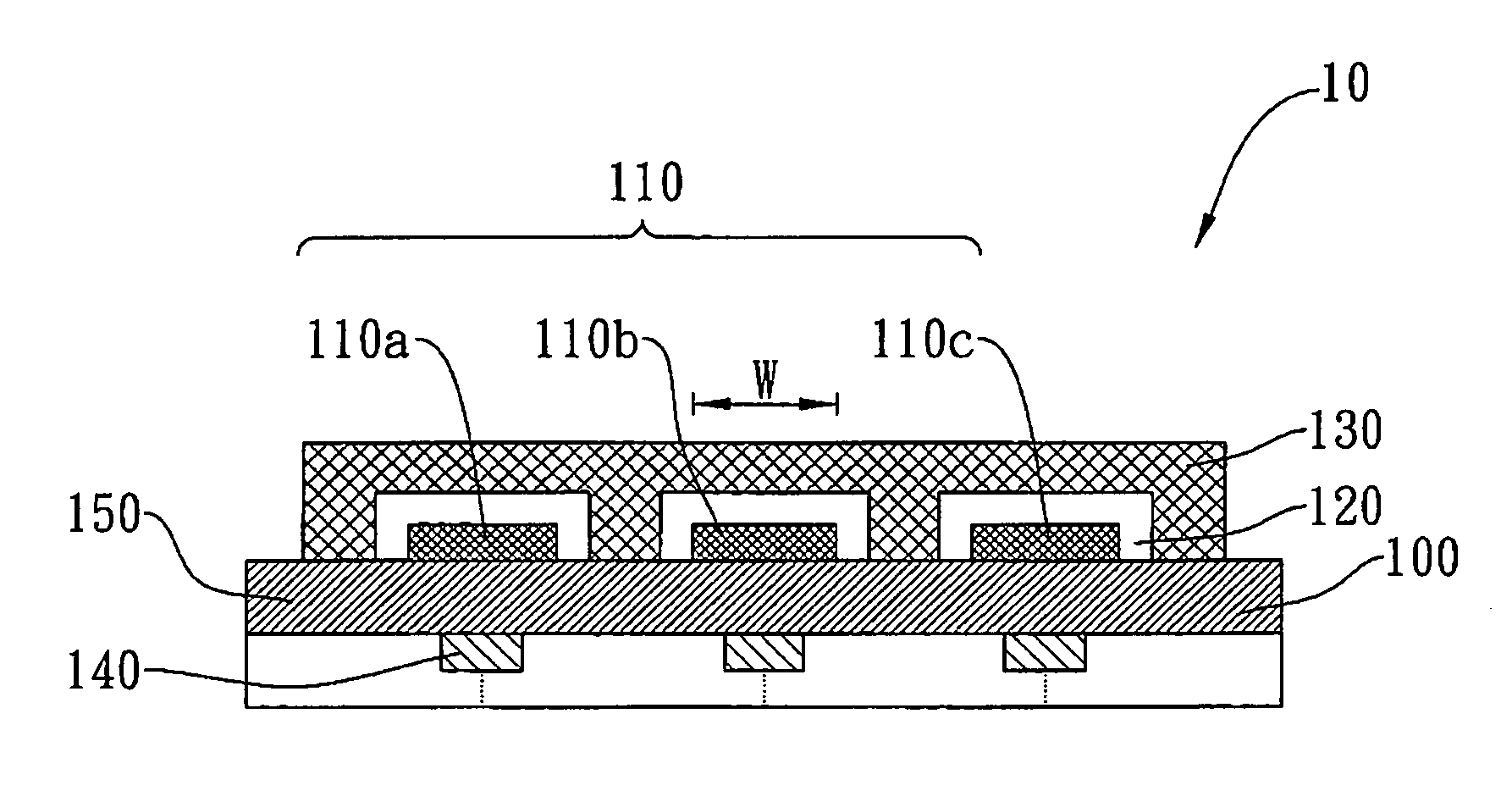
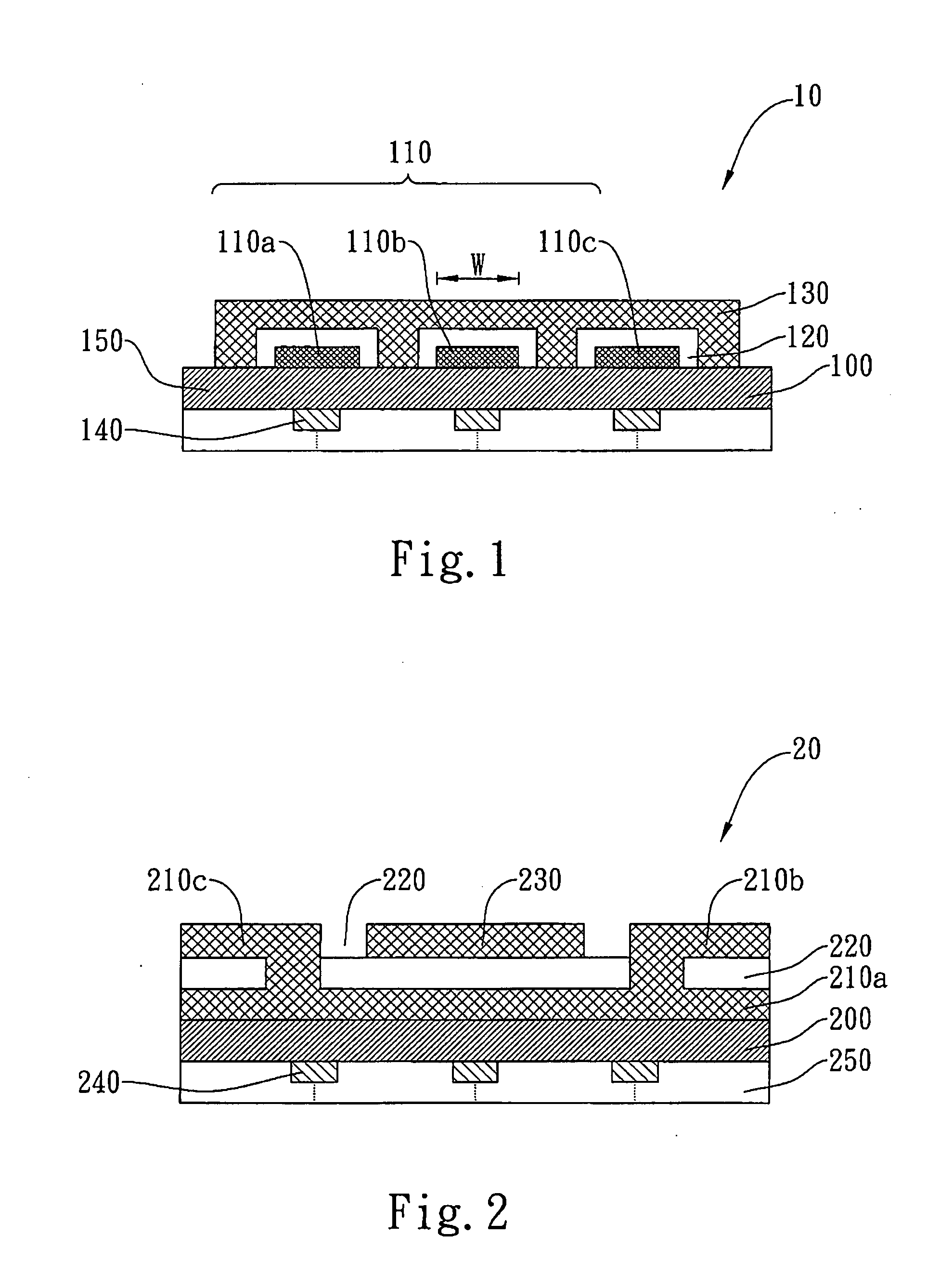
[0034]With reference to FIG. 1, the cross-sectional view of the capacitive touch panel and the sensory electrode thereof according to a preferred embodiment of the present invention is schematically illustrated. The capacitive touch panel 10 according to the present invention is essentially constructed by a substrate 100 and a first sensory electrode 110, an insulating layer 120 and a second sensory electrode 130 stacking on one side of the substrate 100. A black matrix layer 140 and a color filter layer 150 are formed on the other side of the substrate 100. Said first sensory electrode 110 is constructed by pl...


PUM

PropertyMeasurementUnit
widthaaaaaaaaaa
sensory structureaaaaaaaaaa
sensory structuresaaaaaaaaaa

Abstract

A two-dimensional sensory structure for the capacitive touch panel is provided. The provided two-dimensional sensory structure includes a substrate having plural first metal structures and second metal structures on a first surface thereof, a dot-like insulating layer located on the substrate and composed of plural insulating dots, and an electrode layer located on the dot-like insulating layer and composed of plural conductive traces. The insulating dots are each corresponding to the first metal structures respectively, and thereby a first part of the conductive traces arranged along a first direction are electrically connected to each other, and the conductive traces that are arranged along a second direction are electrically insulated therefrom. The thickness of the touch panel according to the invention is effectively reduced.

Description

BACKGROUND OF THE INVENTION[0001]1. Field of the Invention[0002]The present invention relates to a sensory structure of touch panel, and more particularly to a sensory structure of capacitive touch panel and a capacitive touch panel having the same.[0003]2. Description of the Related Art[0004]Touch sensing technology is broadly applied in the present electronic application for data input. In this case, the information is read out or transmitted while the user touches the screen with the finger or the stylus, so that the buttons, keyboards or joysticks, which are desired for the conventional electronic apparatus, could be omitted.[0005]Depending on the principles adopted for sensing, the touch panels are grouped into such as resistive touch panels, capacitive touch panels, infrared (IR) touch panels and ultrasonic wave ones. Regarding the IR touch panels and the ultrasonic wave ones, an IR or ultrasonic wave transmitting unit is arranged on one side of the respective X-direction and ...

Claims


Application Information

Patent Timeline
Patent Type & Authority Applications(United States)
IPC IPC(8): G06F3/045
CPCG06F3/044G06F3/0412G06F3/0445G06F2203/04112
Inventor CHUANG, WEN JU
Owner CANDO
Why Eureka
Try Eureka