Patient support system and method

a technology for supporting systems and patients, applied in the field of seats, can solve problems such as unrelieved pressure, unrelieved pressure, and decreased vascular flow, and achieve the effect of reducing or eliminating bedsores

Active Publication Date: 2011-09-01
PORTER III WINSTON ALLEN
View PDF19 Cites 15 Cited by
  • Summary
  • Abstract
  • Description
  • Claims
  • Application Information

AI Technical Summary

Benefits of technology

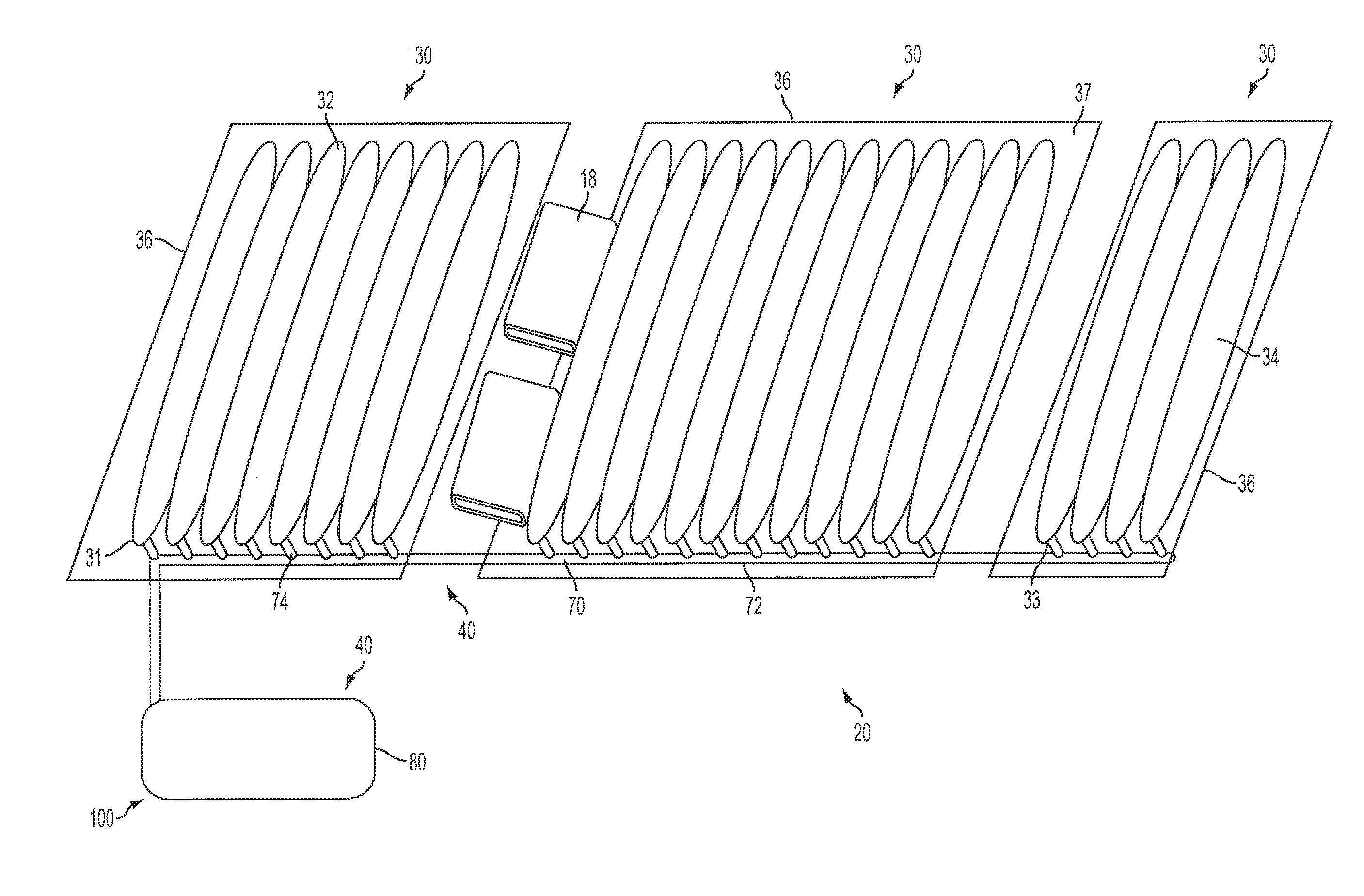
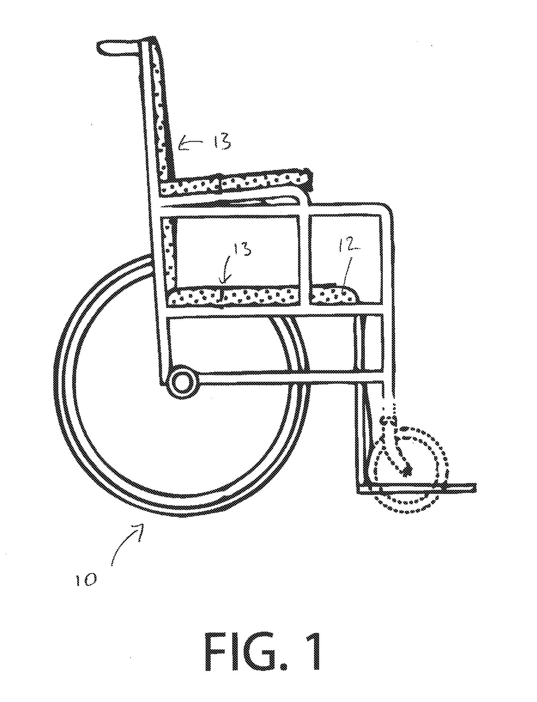
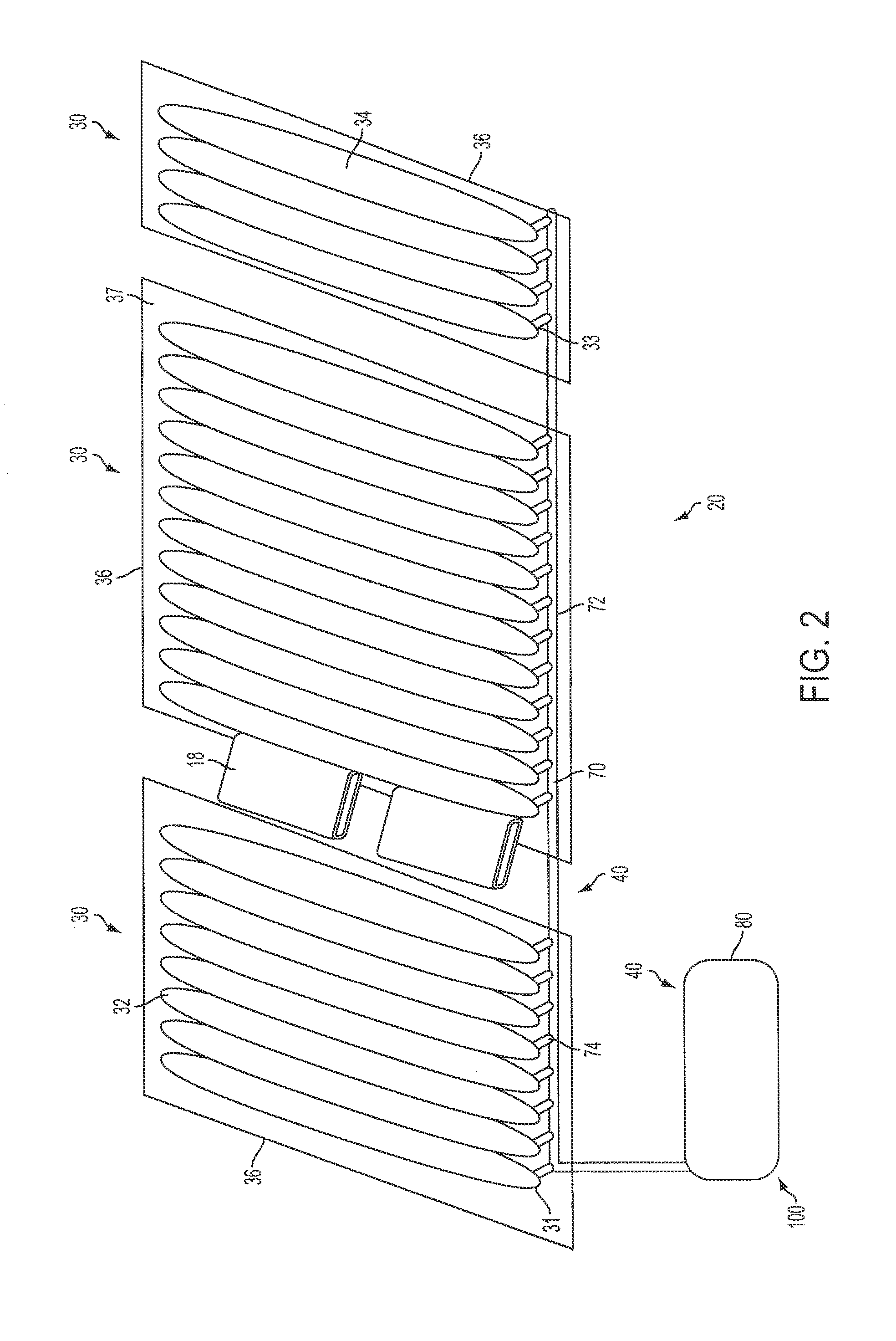
[0007]This application relates to a patient support system for a wheelchair. In one aspect, the patient support system can comprise a plurality of air cells, a control system, and an air supply system, which can exemplarily comprise at least one of: at least one fluid pump, at least one pressure release valve, and a plurality of tubing. In another aspect, the plurality of air cells can be configured to rest on or otherwise engage the wheelchair, so that a patient is supported by the patient support system in a manner to reduce or eliminate bedsores.

Problems solved by technology

Bedsores are lesions on the body that can be caused by factors including friction and shearing forces, however the most common cause of bedsores is unrelieved pressure.
In most cases, this unrelieved pressure occurs when a patient remains in a stationary position for a period of time, for example, on an operating room table during a surgical procedure, and pressure from the weight of the body compresses tissue.
This compression of tissue over time leads to decrease of vascular flow, hypoxia, and / or ischemia and eventually to tissue necrosis (tissue death) if left untreated.
However, these support systems continually leak air and therefore, unless air is added to the system, the air pressure within the low-air-loss patient support system continually decreases as the system deflates.
A pressure measuring device and pressure raising means, such as the fluid pump, must be carried with the low-air-loss patient support system to readjust the support system to the desired set point air pressure, thereby adding a cumbersome object and undue weight to, for example, a wheelchair.
In the event of battery depletion or failure, patients risk pressure support failure should the battery deplete or fail while the patient is on the mobile device.

Method used


Image

  • Patient support system and method
  • Patient support system and method
  • Patient support system and method

Examples


Embodiment Construction

[0027]The present invention can be understood more readily by reference to the following detailed description, examples, drawing, and claims, and their previous and following description. However, before the present devices, systems, and / or methods are disclosed and described, it is to be understood that this invention is not limited to the specific devices, systems, and / or methods disclosed unless otherwise specified, as such can, of course, vary. It is also to be understood that the terminology used herein is for the purpose of describing particular aspects only and is not intended to be limiting.

[0028]The following description of the invention is provided as an enabling teaching of the invention in its best, currently known embodiment. To this end, those skilled in the relevant art will recognize and appreciate that many changes can be made to the various aspects of the invention described herein, while still obtaining the beneficial results of the present invention. It will also...


PUM


Abstract

A patient support system for a wheelchair is provided. At least a portion of the patient support system components form a no-air-loss patient support surface. At least one fluid pump can supply air pressure to a plurality of no-air-loss air cells, and at least one pressure release valve can release air pressure from the no-air-loss air cells. A computer can compare air pressure within the air cells to a desired air pressure set point and can modulate the air pressure by actuating the at least one fluid pump and/or the at least one pressure release valve to bring the air pressure within the air cells to a desired air pressure. After the initial air pressure adjustments are made and the desired air pressure is achieved, no further adjustments during the operation are able to be made by the computer so that the patient positioned thereon the patient support system will not be moved by the patient support system during an operation.

Description

CROSS-REFERENCE TO RELATED APPLICATIONS[0001]This application is a continuation-in-part application of U.S. Utility application Ser. No. 12 / 435,000, filed May 4, 2009, which claims the benefit of U.S. Provisional Application No. 61 / 104,578, filed on Oct. 10, 2008.FIELD OF THE INVENTION[0002]The field of this invention relates generally to seats used for supporting a patient for an extended period of time, such as a wheelchair, and more particularly to a patient support system for a wheelchair for the reduction or prevention of decubitus ulcers, more commonly known as “bedsores.”BACKGROUND OF THE INVENTION[0003]Bedsores are lesions on the body that can be caused by factors including friction and shearing forces, however the most common cause of bedsores is unrelieved pressure. In most cases, this unrelieved pressure occurs when a patient remains in a stationary position for a period of time, for example, on an operating room table during a surgical procedure, and pressure from the we...

Claims


Application Information

Patent Timeline
Patent Type & Authority Applications(United States)
IPC IPC(8): A47C16/00G05D7/00A61G5/12A47C20/00
CPCA61G13/1265A61G5/1043A61F5/34A61G7/05776A61G2007/05792A61G2005/1048A61G2005/1045A61F5/32A61G5/1045A61G5/1048A61G7/057A61G7/05769A61G7/05792
Inventor PORTER, III, WINSTON ALLEN
Owner PORTER III WINSTON ALLEN
Why Eureka
Try Eureka