Camera calibration apparatus

Active Publication Date: 2011-09-08
TOSHIBA ELECTRONICS DEVICES & STORAGE CORPORARTION +2
View PDF11 Cites 67 Cited by
  • Summary
  • Abstract
  • Description
  • Claims
  • Application Information

AI Technical Summary

Problems solved by technology

However, an error occurs in the actual installation time, so that some misalignment may occur in the connection portions between a plurality of images pho

Method used


Image

  • Camera calibration apparatus
  • Camera calibration apparatus
  • Camera calibration apparatus

Examples


first embodiment

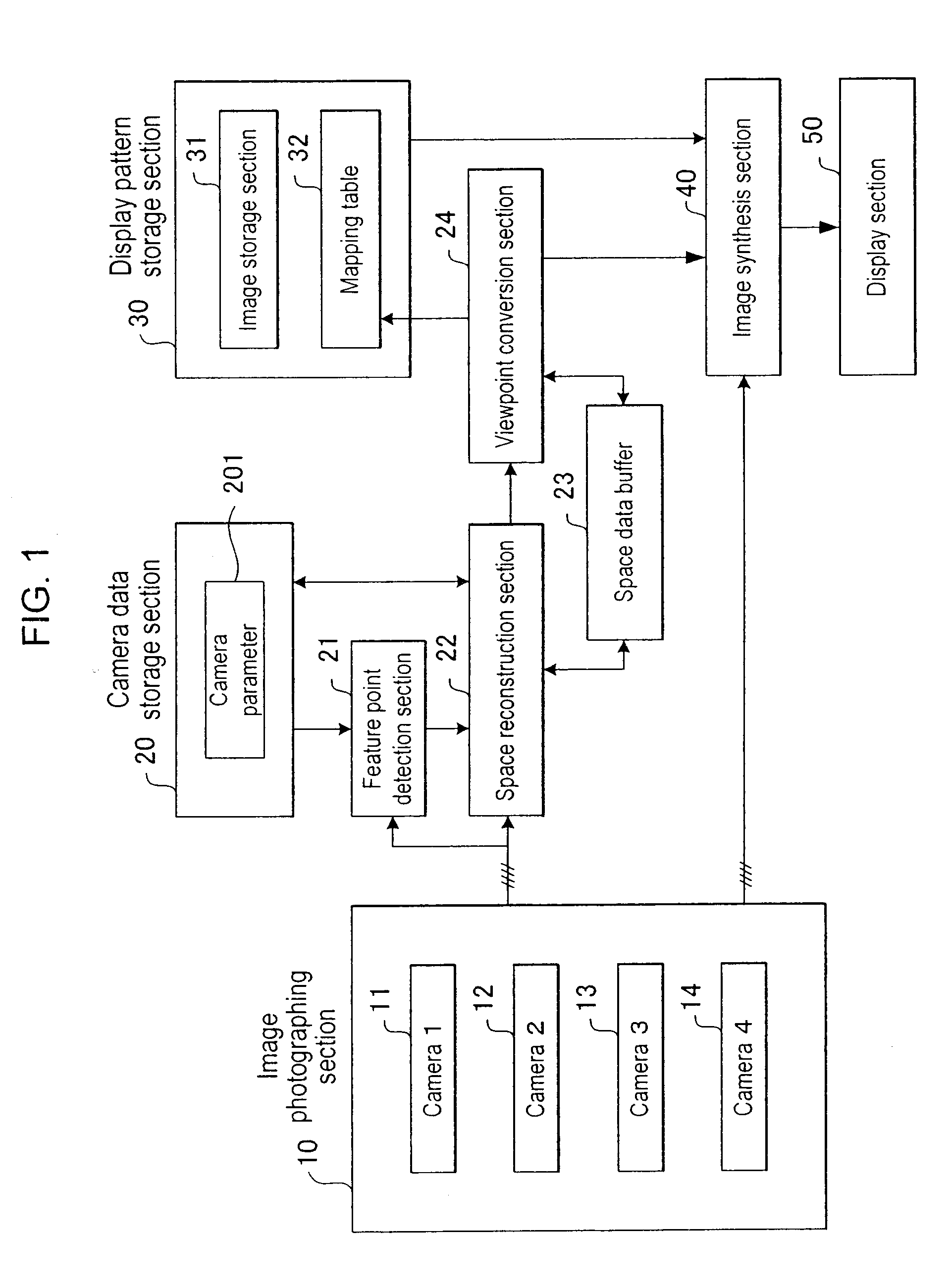
[0034]FIG. 1 is a block diagram illustrating a configuration of a camera calibration apparatus according to the present embodiment. The camera calibration apparatus includes an imaging section 10, a camera data storage section 20, a feature point detection section 21, a space reconstruction section 22, a space data buffer 23, a viewpoint conversion section 24, a display pattern storage section 30, an image synthesis section 40, and a display section 50.

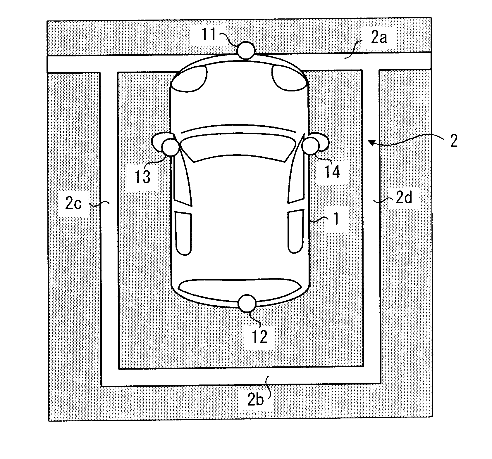
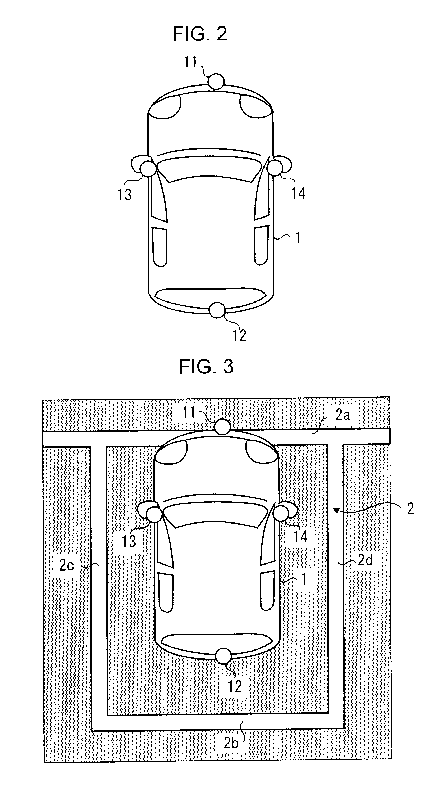
[0035]The image photographing section 10 has, e.g., four cameras 11, 12, 13, and 14 for photographing images of area surrounding a vehicle. The four cameras 11, 12, 13, and 14 photograph the front surrounding area, back surrounding area, left surrounding area, and right surrounding area of the vehicle, respectively. A wide-angle camera such as a fisheye camera is suitably used as the cameras 11 to 14. The positions of the cameras 11 to 14 will be described later.

[0036]The camera data storage section 20 includes a camera parameter tabl...


PUM


Abstract

According to one embodiment, a camera calibration apparatus includes: a plurality of on-vehicle cameras; a feature point detection section that identifies an image of lines representing a parking frame from each of images by the plurality of cameras and detects two feature points; a viewpoint conversion section that generate an overhead view having a viewpoint from just above the vehicle based on the feature points and two directions crossing each other at each of the feature points; and an adjustment section that determines the boundary position between the vehicle and line image from the overhead view to determine the display frame of a vehicle image and changes the overhead view such that the size ratio and position of the display frame become previously specified values.

Description

CROSS-REFERENCE TO RELATED APPLICATION[0001]This application is based upon and claims the benefit of priority from the prior Japanese Patent Application No. 2010-045474, filed on Mar. 2, 2010, the entire contents of which are incorporated herein by reference.BACKGROUND OF THE INVENTION[0002]1. Field[0003]Embodiments described herein relate generally to a camera calibration apparatus which is an on-vehicle camera apparatus having a plurality of on-vehicle cameras for taking images outside a vehicle so as to display them for a driver and performing camera calibration at camera installation time, etc.[0004]2. Background[0005]There is conventionally known an on-vehicle camera apparatus having the following configuration. In this on-vehicle camera apparatus, a plurality of cameras are mounted on a vehicle, and the cameras are used to acquire images of areas (front side, back side, left side, and right side) surrounding the vehicle. Then, images (overhead images) in which the viewpoints t...

Claims


Application Information

Patent Timeline
IPC IPC(8): H04N7/18
CPCH04N7/18H04N7/181B60R1/00B60R2300/402
Inventor KOSAKI, MASANORI
Owner TOSHIBA ELECTRONICS DEVICES & STORAGE CORPORARTION
Why Eureka
Try Eureka