Electrode terminal connecting device and battery module assembly employed with the same

Active Publication Date: 2011-09-15
LG ENERGY SOLUTION LTD
View PDF3 Cites 21 Cited by
  • Summary
  • Abstract
  • Description
  • Claims
  • Application Information

AI Technical Summary

Benefits of technology

[0034]It is possible for the electrode terminal connecting device according to the present invention to connect battery modules in series and/or parallel to one another, and therefore, easy design based on desired power and capacity is possible. Consequently, the present invention provides a battery module assembly wherein electrical connection is achieved using electrode terminal connecting devices.
[0035]In an exemplary embodiment, the battery module assembly may be constructed in a structure in which a pl

Problems solved by technology

However, electrode terminal connection regions have a high likelihood of short circuiting when external impact is applied to the electrode terminal connection regions.
Consequently, when external impact, for example due to a car collision, is applied to the middle- or large-sized battery pack, the pack case is deformed, with the result that the pack case may come into contact with electrode terminal connection regions of battery modules, whereby short circuits may occur.
However, the above-suggested t

Method used


Image

  • Electrode terminal connecting device and battery module assembly employed with the same
  • Electrode terminal connecting device and battery module assembly employed with the same
  • Electrode terminal connecting device and battery module assembly employed with the same

Examples


Example

[0047]Now, exemplary embodiments of the present invention will be described in detail with reference to the accompanying drawings. It should be noted, however, that the scope of the present invention is not limited by the illustrated embodiments.

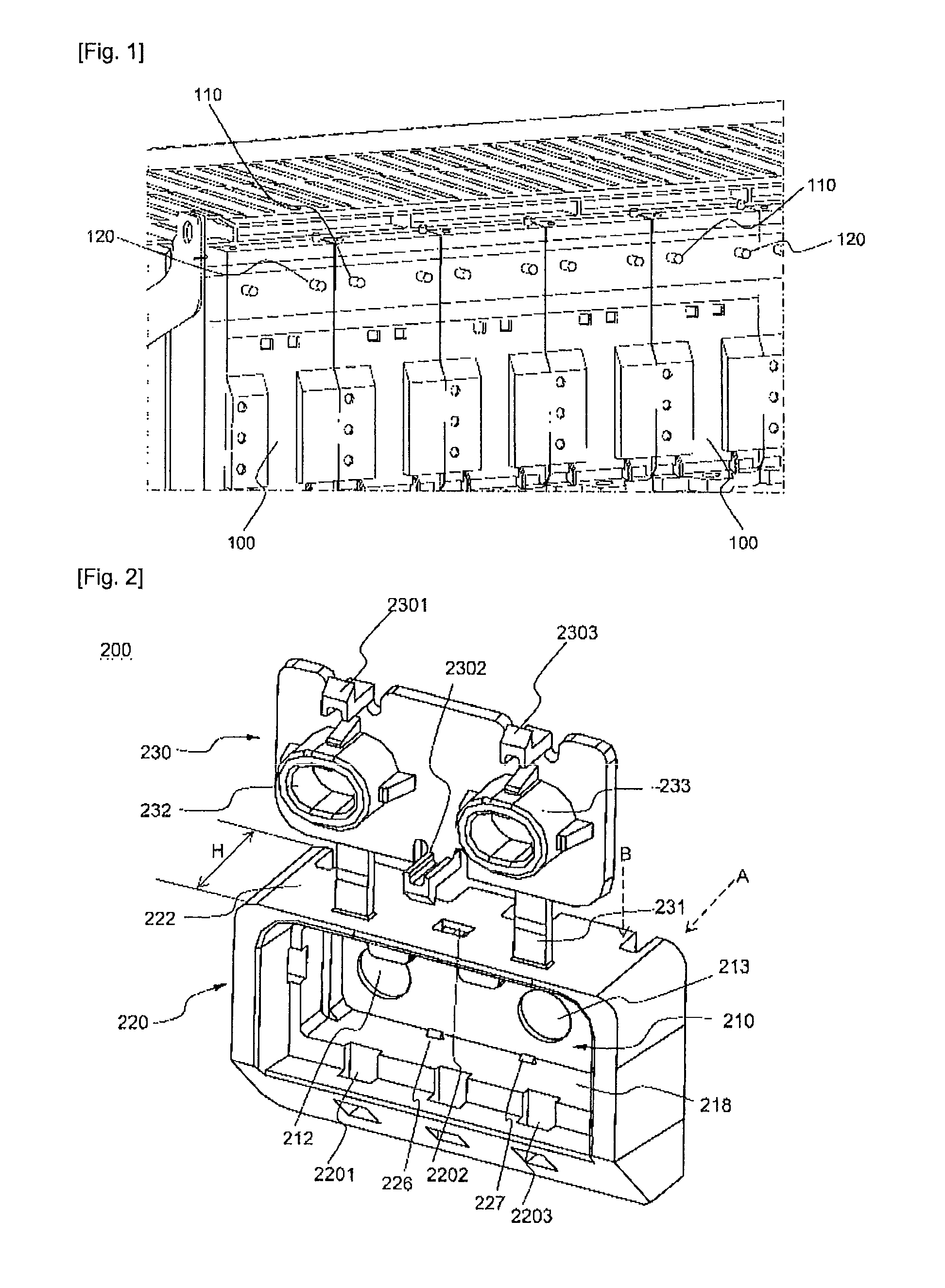
[0048]FIG. 1 is a partial typical view illustrating a side of a structure in which a plurality of battery modules are stacked.

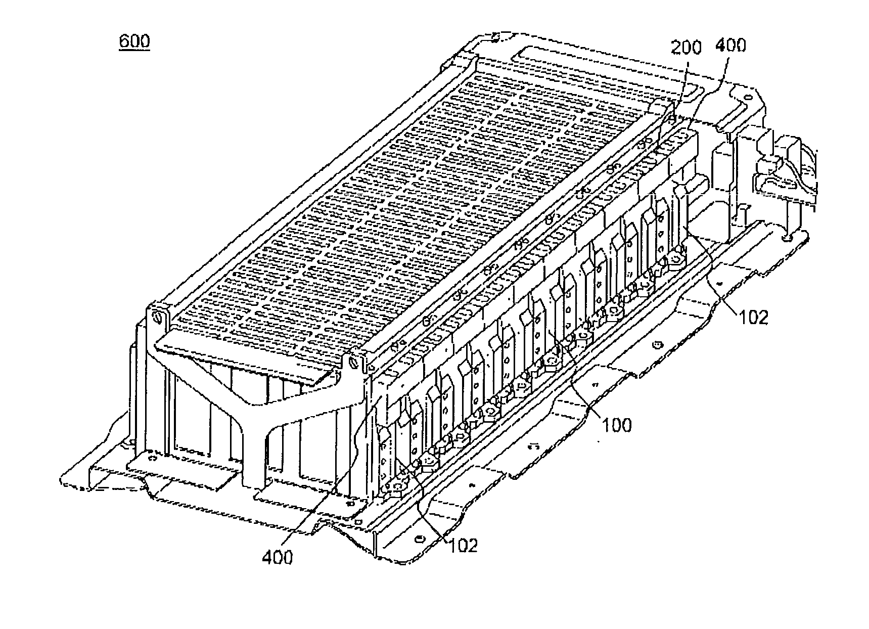
[0049]Referring to FIG. 1, a battery module assembly for providing high-power, large-capacity electric power includes a plurality of battery modules 100. Electrode terminals 110 and 120 protrude from one side of each battery module 100. The electrode terminals 110 and 120 of the battery modules 100 are arranged on the same line such that the electrode terminals 110 and 120 are parallel to the direction in which the battery modules 100 are stacked. Also, each of the protruding electrode terminals 110 and 120 is provided at the outer circumference thereof with a thread (not shown) by which each of the protruding electro...


PUM


Abstract

Disclosed herein is an electrode terminal connecting device for electrically interconnecting two or more battery modules, including a conductive connecting member for electrically interconnecting electrode terminals of the battery modules, the conductive connecting member having two through-holes formed at positions corresponding to the distance between the electrode terminals, an insulative sheathing member for surrounding the conductive connecting member, a portion of an open rear of the insulative sheathing member being closed for easy installation of the conductive connecting member, the insulative sheathing member including a side wall protruding from the outer circumference of the conductive connecting member such that the side wall has a predetermined height, and an insulative cap connected to the top of the insulative sheathing member by a hinge structure for opening and closing an open front of the insulative sheathing member, the insulative cap having hollow buffers protruding from the inside thereof for surrounding portions of the electrode terminals protruding through the through-holes.

Description

TECHNICAL FIELD[0001]The present invention relates to a device for electrically interconnecting two or more battery modules, and, more particularly, to an electrode terminal connecting device including a conductive connecting member for electrically interconnecting electrode terminals of the battery modules, the conductive connecting member having two through-holes formed at positions corresponding to the distance between the electrode terminals, an insulative sheathing member for surrounding the conductive connecting member, a portion of an open rear of the insulative sheathing member being closed for easy installation of the conductive connecting member, the insulative sheathing member including a side wall protruding from the outer circumference of the conductive connecting member such that the side wall has a predetermined height, and an insulative cap connected to the top of the insulative sheathing member by a hinge structure for opening and closing an open front of the insula...

Claims


Application Information

Patent Timeline
IPC IPC(8): H01M2/24H01R24/00H01M50/529H01M50/296H01M50/502
CPCH01M2/206H01M2/1077Y02E60/10H01M50/502H01M50/296H01M50/50
Inventor LEE, BUMHYUNSHIN, YONGSHIKLEE, JIN KYUYOON, JONGMOONYANG, JAE HUN
Owner LG ENERGY SOLUTION LTD
Why Eureka
Try Eureka