
Health monitoring systems and methods with vehicle velocity

a technology of health monitoring and vehicle velocity, applied in vehicle testing, structural/machine measurement, instruments, etc., can solve the problems of common vehicle faults in tires, brakes, suspensions, and frames, and component damage of such vehicles often lies in the tail of the reliability distribution curve, and the reliability prediction of these vehicles may not accurately predict component issues

Inactive Publication Date: 2011-09-15
HONEYWELL INT INC
View PDF22 Cites 154 Cited by
  • Summary
  • Abstract
  • Description
  • Claims
  • Application Information

AI Technical Summary

Problems solved by technology

Most common vehicle faults occur in the tires, brakes, suspensions, body chassis, and frames.
However, despite prediction models, component damage for such vehicles often lies in the tails of the reliability distribution curve.
The reliability predictions for these vehicles may not accurately predict component issues.
Not surprisingly, operation and support costs for military vehicles account for a large portion of budget cost.
However, individual health monitoring systems for each vehicle may be expensive.
There are a number of difficulties with these conventional approaches.
The operational responses of the vehicles are difficult to model due to the non-stationary nature of the loading and the inability to control these loads during operation.
Second, many vehicles are not equipped with sensors nor the acquisition systems to acquire, process, and store data; therefore, to implement health monitoring for condition-based maintenance, one needs to overcome the economic and technical barriers associated with equipping ground vehicles to continuously monitor their responses.
Another difficulty of these health monitoring systems is the limited usefulness of the dynamic response data gathered from the vehicles.

Method used


Image

  • Health monitoring systems and methods with vehicle velocity
  • Health monitoring systems and methods with vehicle velocity
  • Health monitoring systems and methods with vehicle velocity

Examples


Embodiment Construction

[0028]The following detailed description is merely exemplary in nature and is not intended to limit the invention or the application and uses of the invention. Furthermore, there is no intention to be bound by any theory presented in the preceding background or the following detailed description.

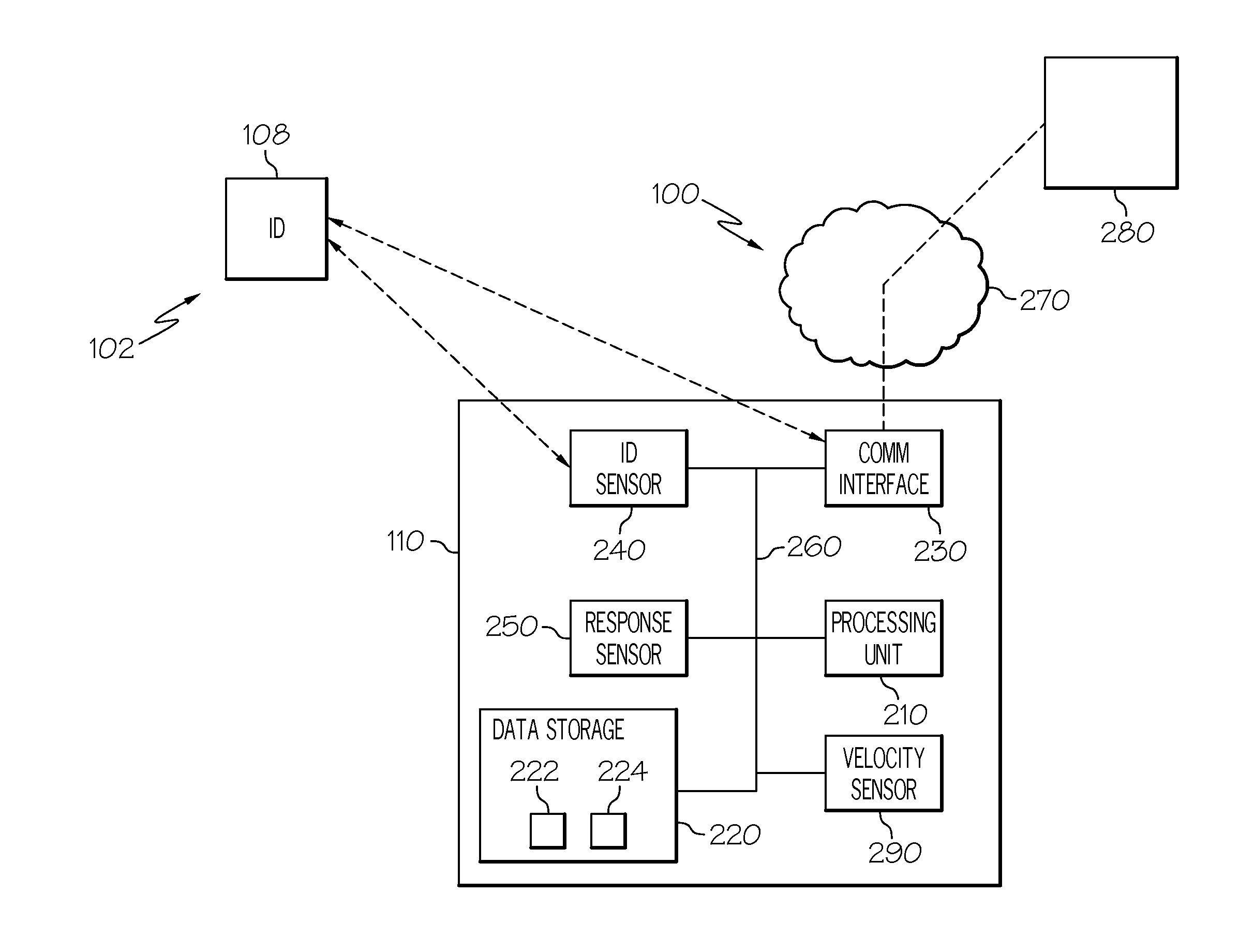
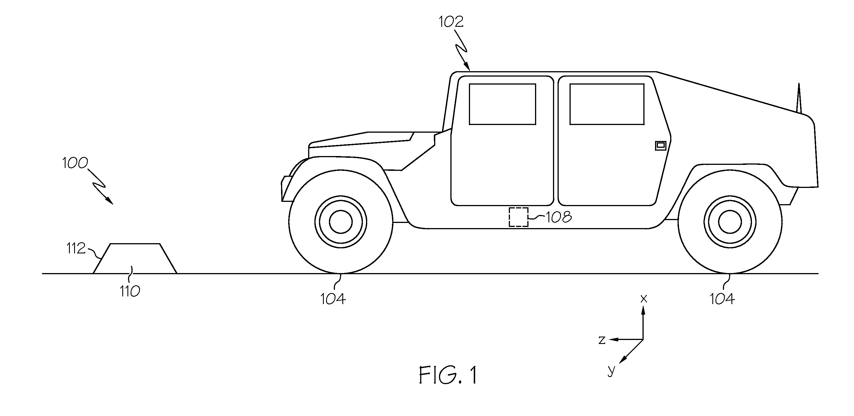
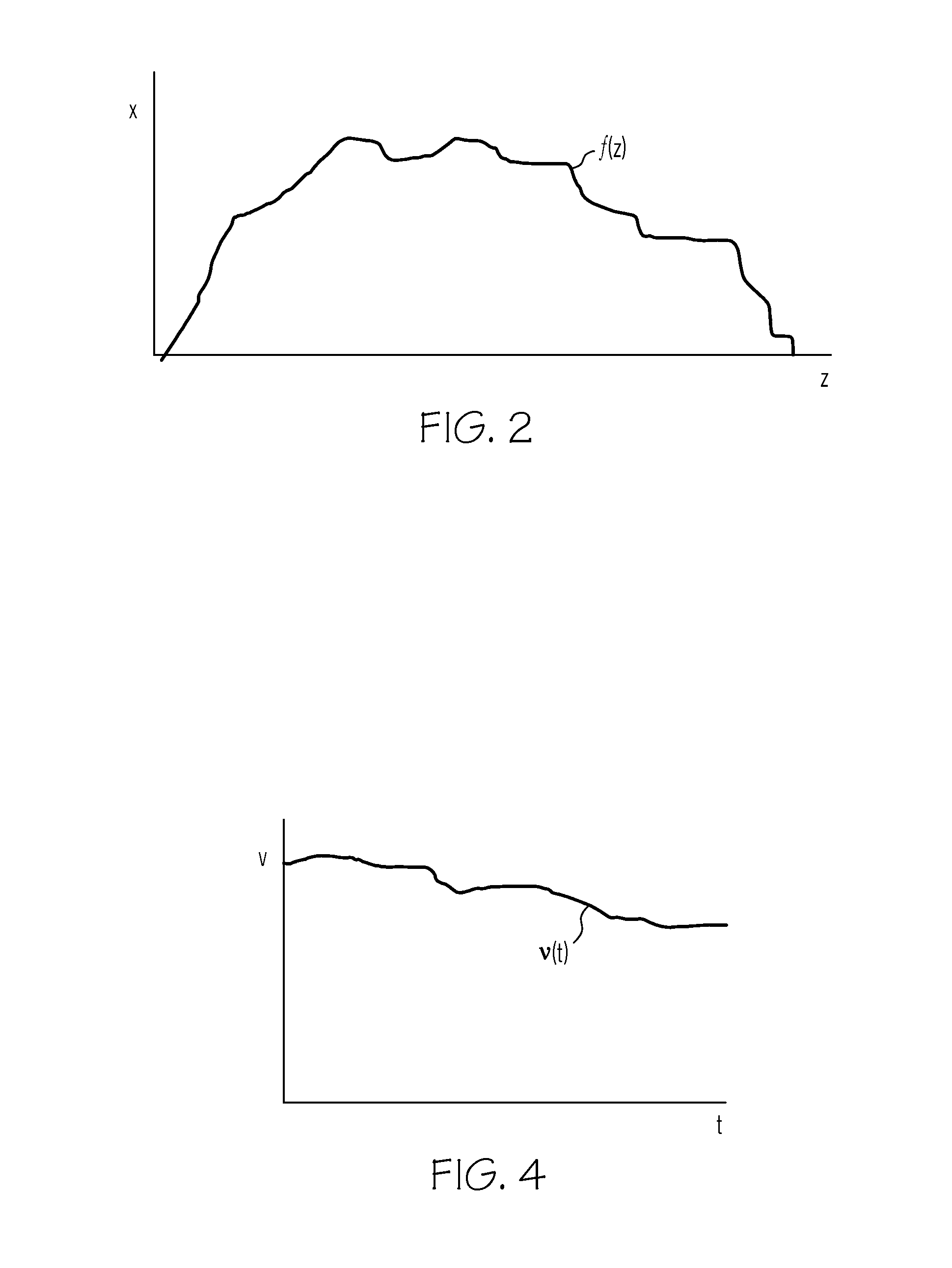
[0029]Broadly, exemplary embodiments discussed herein relate to vehicle monitoring systems and methods. The vehicle monitoring systems and methods include an instrumented cleat placed within the path of a vehicle to be monitored. As the vehicle passes over the cleat, sensors within the cleat measure characteristics of the vehicle, including the vehicle's dynamic response to the stimulus function generated by driving over the cleat. The health monitoring system and method can diagnose faults within the vehicle based on the response to the forcing function. The health monitoring systems and methods may additionally include sensor(s) that identify the individual vehicle. The health monitoring s...


PUM


Abstract

A health monitoring system is provided for a vehicle configured to travel over a surface with a velocity. The system includes a body configured to stimulate a dynamic response from the vehicle as the vehicle travels over the body; a response sensor associated with the body and configured to measure the dynamic response from the vehicle; an identification sensor associated with the body and configured to collect data corresponding to the identity of the vehicle; a velocity sensor associated with the body and configured to determine the velocity of the vehicle; and a processing unit associated with the body and configured to evaluate the health of the vehicle based on the dynamic response, the identity, and the velocity.

Description

TECHNICAL FIELD[0001]The present invention generally relates to vehicle health monitoring systems, and more particularly relates to health monitoring systems and methods based on driving a vehicle over a known surface with a measured velocity.BACKGROUND[0002]Military, such as the U.S. Army, commercial, industrial, and consumer operators are each pursuing technologies that will enable Condition-Based Maintenance (CBM) of ground vehicles. Conventional maintenance schedules for ground vehicles are determined based on reliability predictions of a population of vehicles under anticipated operational loads. Most common vehicle faults occur in the tires, brakes, suspensions, body chassis, and frames. However, despite prediction models, component damage for such vehicles often lies in the tails of the reliability distribution curve. For example, a certain group of vehicles may be deployed to operate on a harsh terrain that is particularly taxing on the mechanical components of those vehicle...

Claims


Application Information

Patent Timeline
IPC IPC(8): G06F7/00
CPCG07C5/085G07C5/0808
Inventor GORDON, GRANTBUSCH, DARRYLSIMONS, MARKWRIGHT, GEORGE
Owner HONEYWELL INT INC
Learn More