Product dispensing method and vending machine

Inactive Publication Date: 2011-09-22
N& W GLOBAL VENDING
View PDF16 Cites 24 Cited by
  • Summary
  • Abstract
  • Description
  • Claims
  • Application Information

AI Technical Summary

Benefits of technology

[0008]One or more embodiments of the present invention provide a vending machine product dispensing method that is cheap

Problems solved by technology

So far, however, this has only be achieved at the expense of various drawbacks, mainly due to known vending machines of the above type, for example the vending machine disclosed in U.S. Pat. No. 6,415,952, normally comprising a pickup station comprising a compartment accessible from the outside, and into which

Method used


Image

  • Product dispensing method and vending machine
  • Product dispensing method and vending machine
  • Product dispensing method and vending machine

Examples


Embodiment Construction

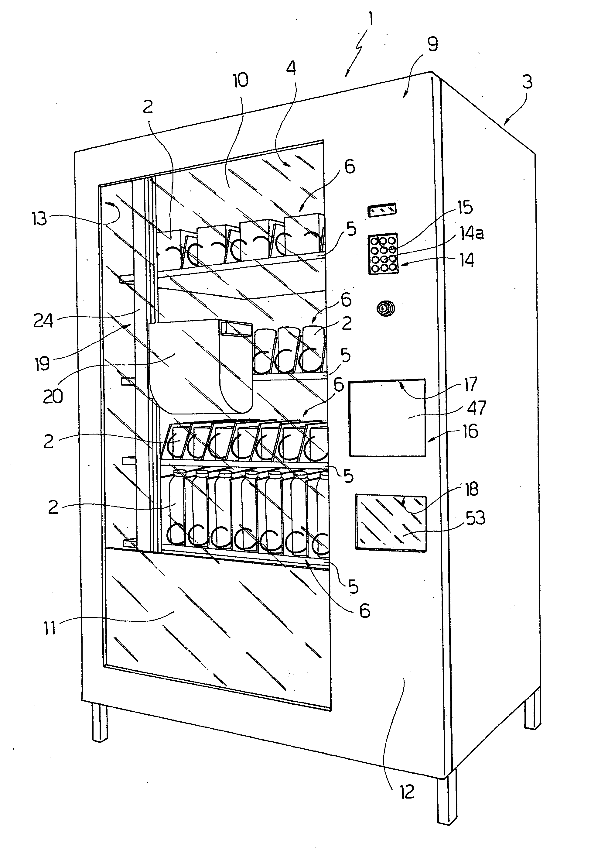
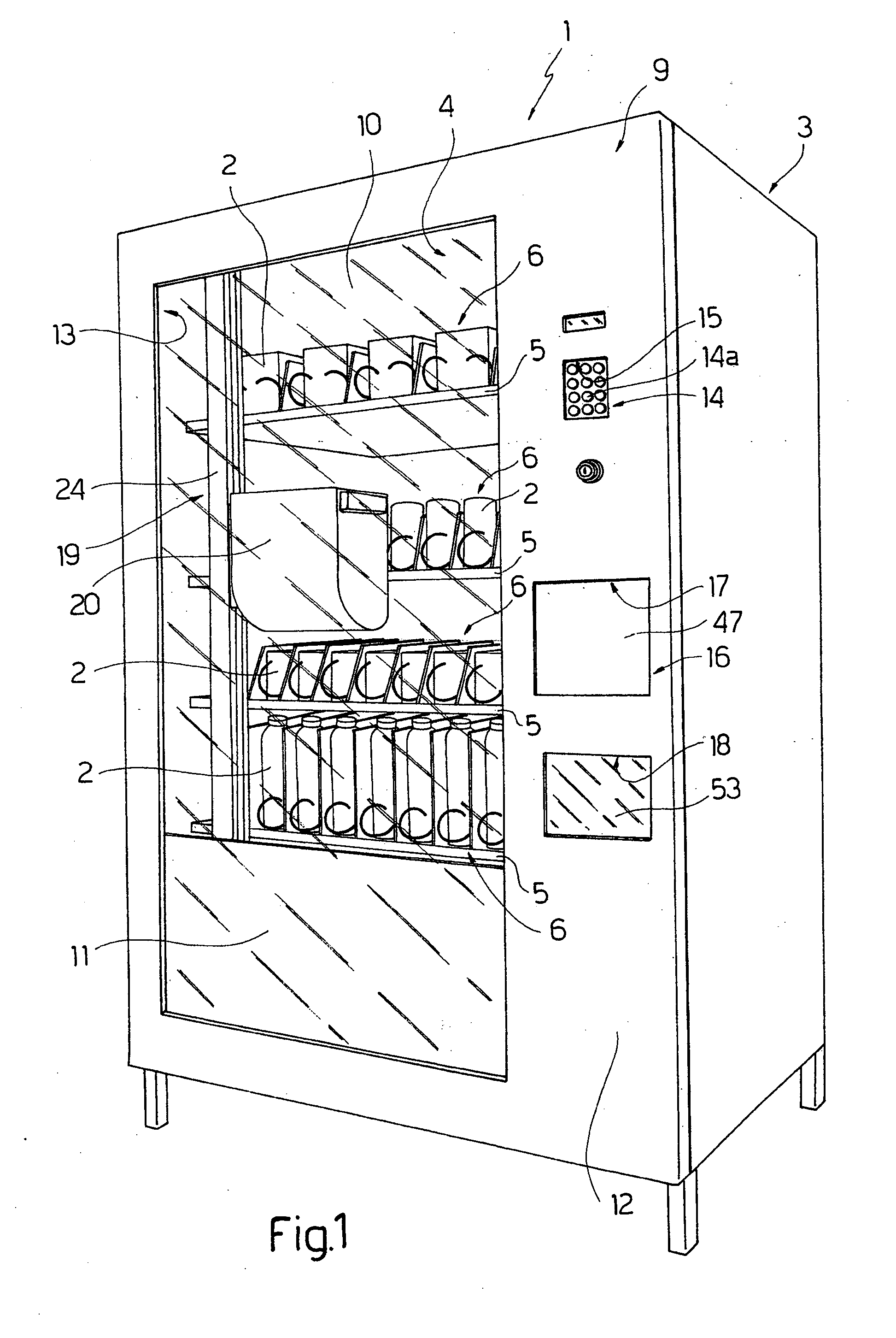
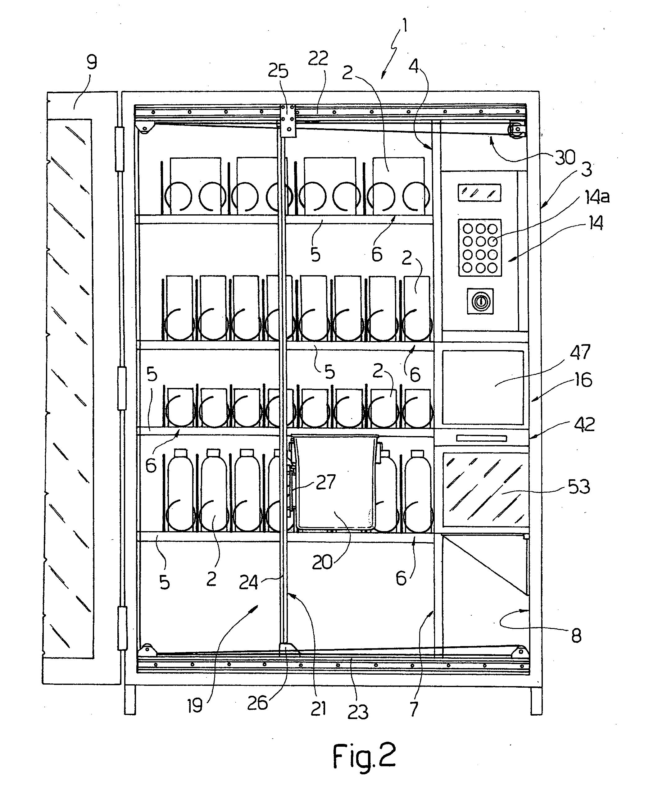
[0019]Number 1 in FIGS. 1 and 2 indicates as a whole a vending machine for products 2, comprising a casing 3 defining a top compartment 4 housing a number of superimposed trays 5, each supporting a number of side by side lines 6 of products 2; a compartment 7 beneath compartment 4; and a compartment 8 alongside compartments 4 and 7.

[0020]As shown in FIG. 1, casing 3 is closed at the front by a front wall defined by a door 9, which comprises a top lateral portion 10 made of transparent material and facing compartment 4; a lateral portion 11 made of non-transparent material and facing compartment 7; and a lateral portion made of non-transparent material, such as metal, and defined by a panel 12 facing compartment 8.

[0021]With the front ends of trays 5, door 9 defines a substantially vertical drop shaft 13, to which user-selected products 2 are fed by known push conveyors (defined, in the example shown, by screw conveyors).

[0022]As shown in FIG. 2, behind panel 12, shaft 13 houses a co...


PUM


Abstract

A method and vending machine for dispensing products, whereby a selected product is transferred by a bin from a relative line on a relative tray of the vending machine to a pickup station communicating with the outside through a window having a movable hatch; the bin being moved between a first position, in which the bin receives the selected product, and a second position, in which the bin is located just below the window at the pickup station, so the selected product, once the hatch is opened, can be withdrawn through the window from the outside, directly from the bin arrested in the second position.

Description

CROSS-REFERENCE TO RELATED APPLICATIONS[0001]This application is a U.S. Nationalization of PCT International Application No. PCT / IB2009 / 005591 filed 14 May 2009, entitled “PRODUCT DISPENSING METHOD AND VENDING MACHINE”, which claims priority to Italian Patent Application No. TO2008A000367 filed 15 May 2008, the entireties of both the foregoing application are incorporated herein by referenceTECHNICAL FIELD[0002]Embodiments of the present invention relate to a product dispensing method and vending machine.BACKGROUND ART[0003]Product vending machines are known to comprise a casing or similar container defining a compartment closed at the front by a door, which normally comprises a part made of transparent material, and a lateral part defined by a panel or upright made of non-transparent material, such as metal.[0004]The compartment normally houses a number of superimposed trays, which face the transparent part of the door, support respective numbers of products, such as bottles, cans,...

Claims


Application Information

Patent Timeline
IPC IPC(8): B65D83/00B65G59/00
CPCG07F11/165G07F11/42G07F11/36
Inventor SICHICH, ROBERTO
Owner N& W GLOBAL VENDING
Why Eureka
Try Eureka