Pluggable optical transceiver having functional latch screw
a technology of optical transceivers and latch screws, which is applied in the field of pluggable optical transceivers, can solve the problems of osa-based semiconductor devices that are quite difficult to follow such high speed alone, demerit that the whole component is needed to be replaced, and the tosas and rosas operable in such high speed regions are difficult to be availabl
- Summary
- Abstract
- Description
- Claims
- Application Information
AI Technical Summary
Benefits of technology
Problems solved by technology
Method used
Image

Examples
first embodiment
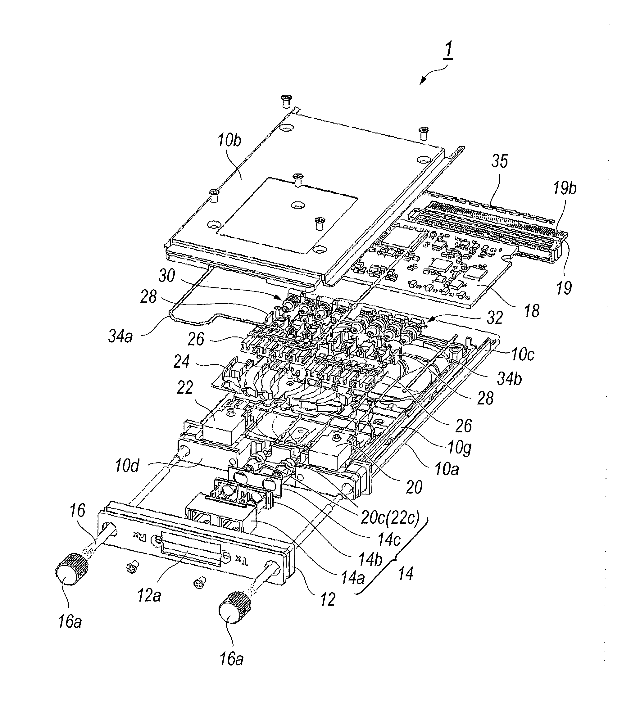
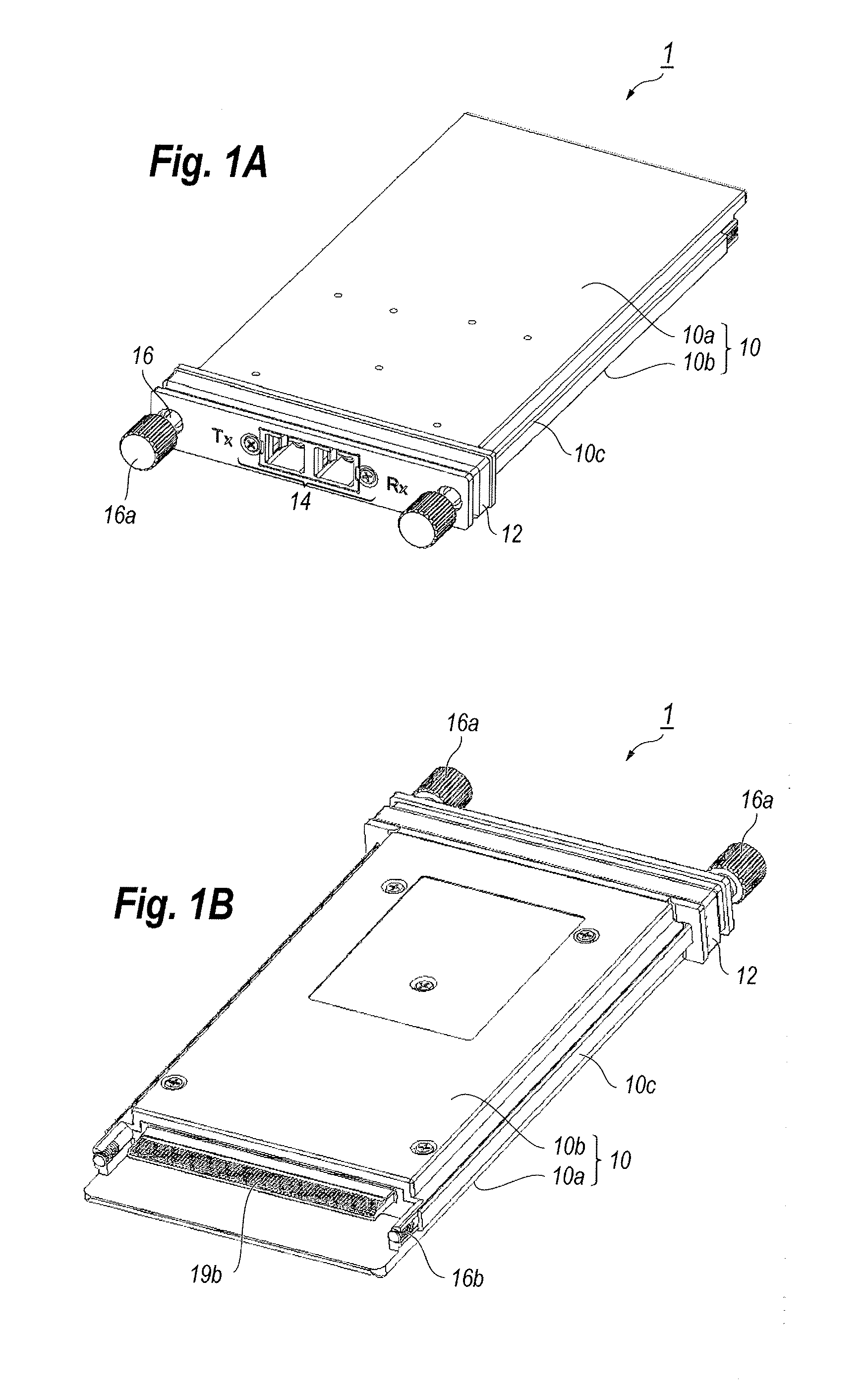
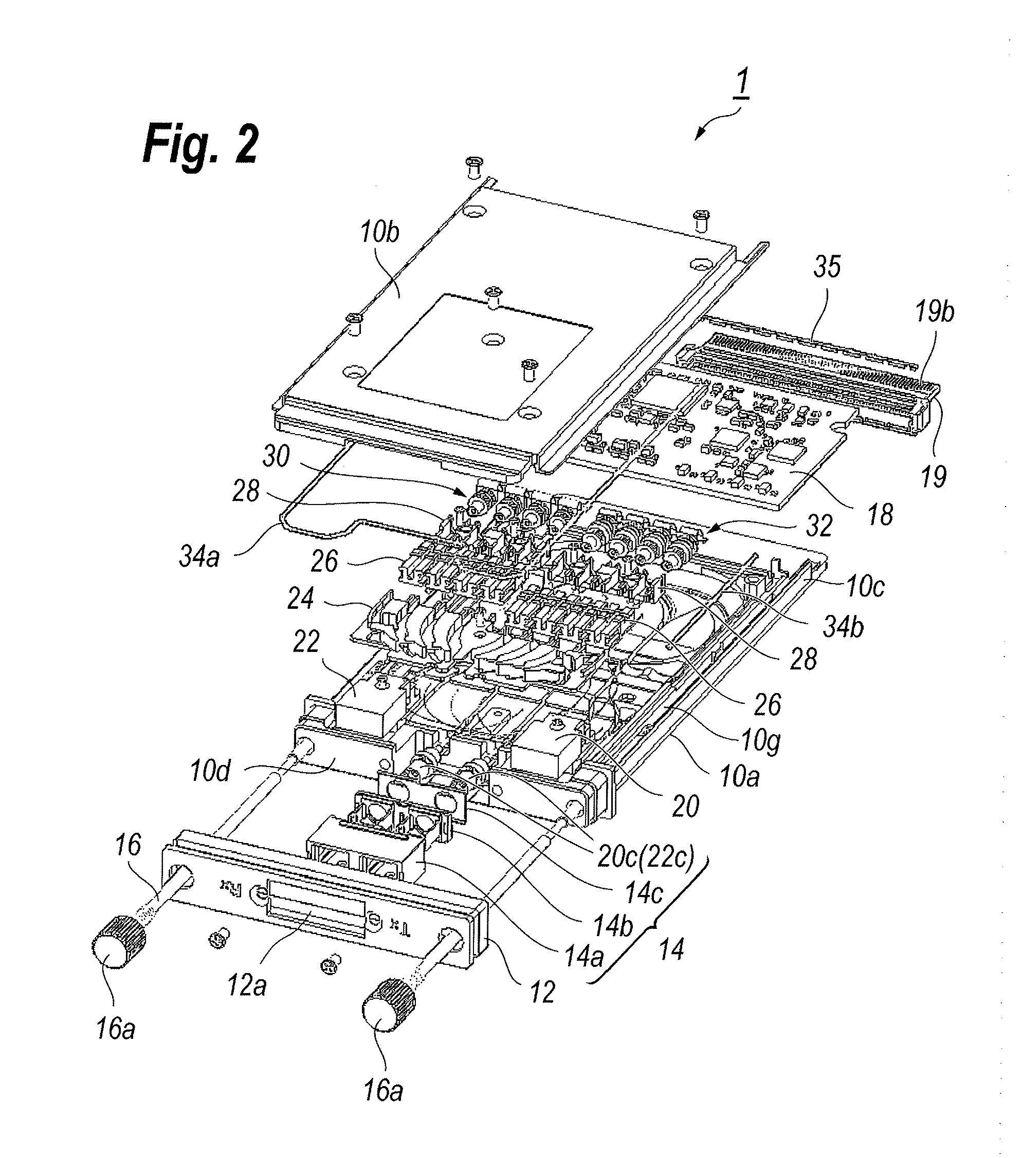
[0074]FIGS. 1A and 1B are perspective views of an optical transceiver 1 according to an embodiment of the present invention, where FIG. 1A views the optical transceiver 1 from upper front, while FIG. 1B views the transceiver from rear bottom. In the description presented below, the front side corresponds to a side where an optical receptacle 14 is implemented, the rear side corresponds to a side where an electrical plug 19b is installed, the upper or the top corresponds to a side where the first housing 10a is installed with respect to the second housing 10b, and the lower or the bottom corresponds to the side the second housing 10b is implemented. FIG. 3 illustrates the host system on which the optical transceiver 1 is to be mounted. The host system 2 typically provides the system board 2a, where a pair of rails 3b and the host connector 3a is mounted. The face panel 2b with a port 2c is provided in the host board 2a. The optical transceiver 1 of the present invention may be plugga...
second embodiment
[0174]Next, a process to assembly the optical transceiver 1 according to the second embodiment of the present invention will be described in detail. The process described below assumes a condition that the optical transceiver 1 provides the housing 100, the front tray 124, the rear tray 136, and the inner connector 126 of the second embodiment.
[0175]The process first installs the rear tray 136 on the fourth section R4, the optical multiplexer 20 and the optical demultiplexer 22 on respective positions. Then, the process wires the inner fibers, F2 to F8.
[0176]As shown in FIG. 31A, setting the inner fiber F6 extended from the optical multiplexer 20 within the grooves, G2 and G4, formed in the sections, R2 and R3, of the transmitter side, the inner fiber F6 is extended to the fourth section R4. Guiding the fiber F6 along the rear tray 136 to turn to the receiver side, and drawing along the side of the receiver side, the fiber F6 reaches the first section R1. Eaves 136c provided in the ...
PUM
| Property | Measurement | Unit |
|---|---|---|
| bent radius | aaaaa | aaaaa |
| bent radius | aaaaa | aaaaa |
| width | aaaaa | aaaaa |
Abstract
Description
Claims
Application Information
 - R&D Engineer
- R&D Manager
- IP Professional
- Industry Leading Data Capabilities
- Powerful AI technology
- Patent DNA Extraction
Browse by: Latest US Patents, China's latest patents, Technical Efficacy Thesaurus, Application Domain, Technology Topic.
© 2024 PatSnap. All rights reserved.Legal|Privacy policy|Modern Slavery Act Transparency Statement|Sitemap