

Flexible pinch fitting for containers
a flexible, container technology, applied in the direction of flexible container closure, transportation and packaging, sacks, etc., to achieve the effect of reducing or eliminating dead spa
- Summary
- Abstract
- Description
- Claims
- Application Information
AI Technical Summary
Benefits of technology
Problems solved by technology
Method used
Image

Examples
first embodiment
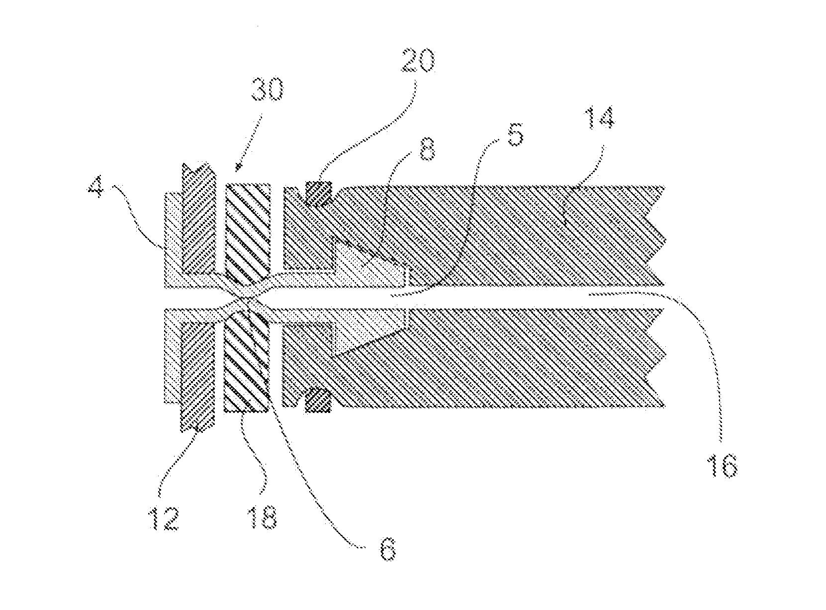
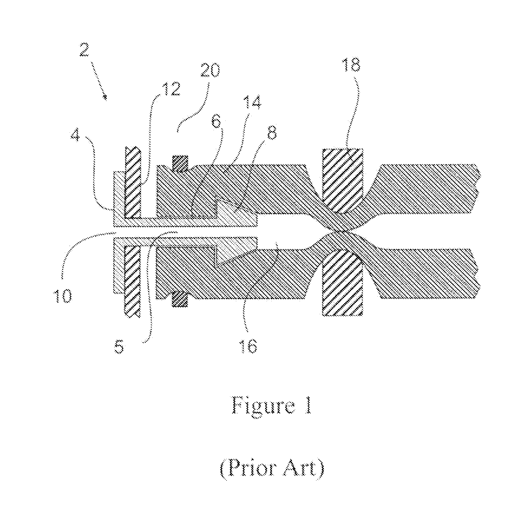
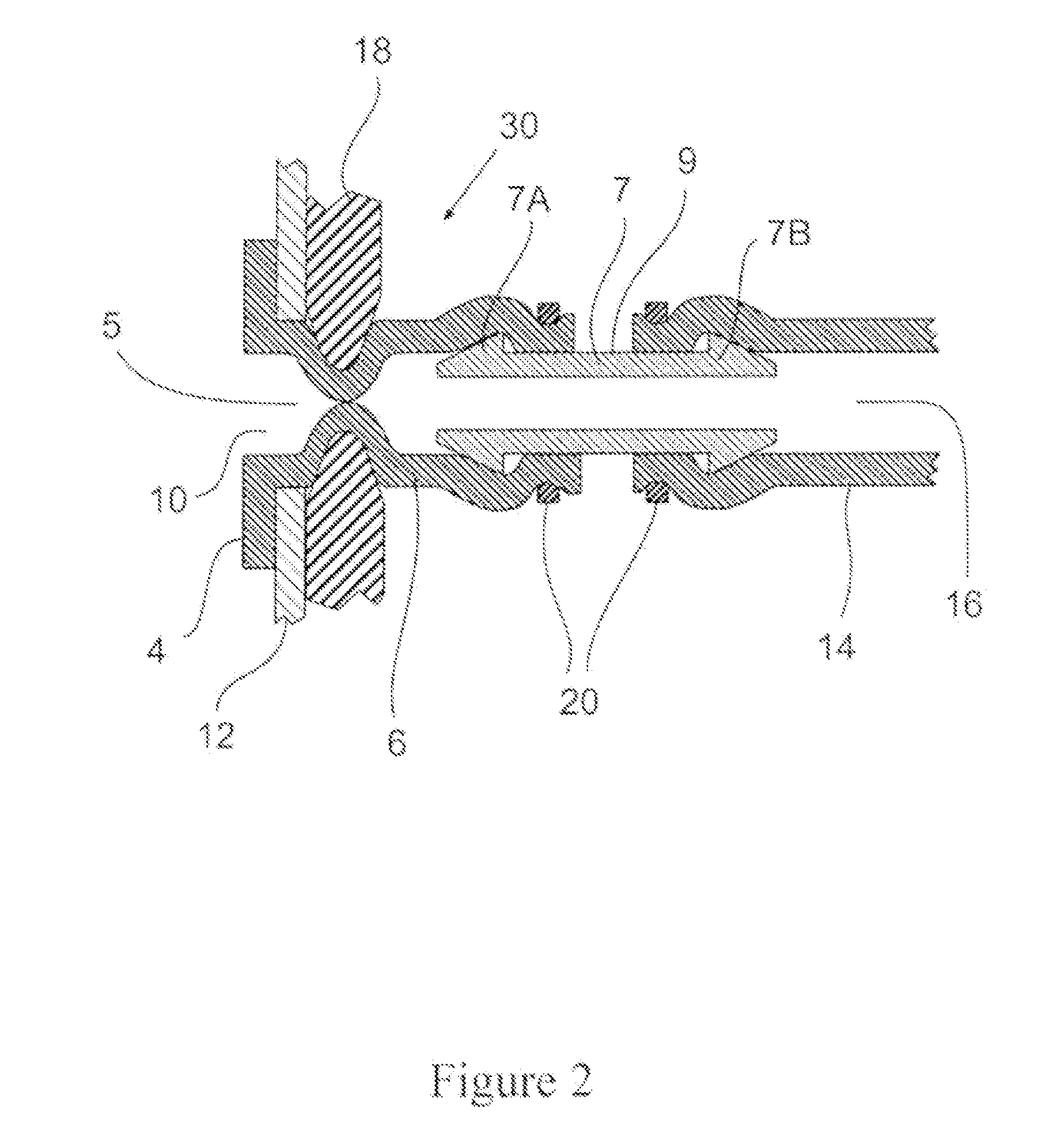
[0033]FIG. 2 shows the present invention. To the extent that the same features are used in the drawings the same element number has been used. The fitting 30 of the present invention is made from a flexible compressible, resilient plastic material. Preferably, the fitting 30 is made from a plastic material that is capable of being bonded to the bag 12 in the same manner as is done with the traditional rigid plastic fittings of FIG. 1. Alternatively for this embodiment and all other embodiments in the present invention the fitting may be formed of another material and retained in aliquid tight sealed manner to the bag by other means such as adhesives or mechanical means such as a threaded portion and a nut. As shown the pinch valve 18 is located on the neck 6 of the fitting between the bag 12 and the barb portion 8. In this embodiment, the fitting has a flange 4 which is sealed to the bag 12. As shown the fitting 30 has a flange 4 that is in the interior of the bag 12. It can equally...
second embodiment
[0034]FIG. 3 shows the present invention. The fitting 30 of the present invention is made from a flexible compressible, resilient plastic material. Preferably, the fitting 30 is made from a plastic material that is capable of being bonded to the bag 12 in the same manner as is done with the traditional rigid plastic fittings of FIG. 1. As shown, the pinch valve 18 is located on the neck 6 of the fitting 30 between the bag 12 and the hose barb 8.
[0035]As shown in FIG. 4, being of an elastomeric material the pinch valve 18 can be actuated adjacent the opening 10 in the bag over the fitting 30 so as to reduce or eliminate the dead space volume present in the prior art.
[0036]The fitting materials include but are not limited to any elastomeric material such as thermoplastic elastomers, thermosets such as urethanes, especially closed cell foamed urethane, and rubber, both natural and synthetic. Preferably, they are thermoplastic elastomers such thermoplastic polyolefin and elastomeric all...
third embodiment
[0039]FIG. 6 shows the present invention. A rigid insert 34 is fit over a portion of the exterior and interior of the fitting 30 so that a portion of the neck 6 downstream of where the valve 18 is and the barb contain the insert 34. This provides a more traditional fitting for the tubing and helps to ensure that it is secured to the fitting and resists the normal actions that might otherwise dislodge it. Preferably as shown the insert 34 has a portion 35 that fits under the barb of the fitting to help retain it in place. This insert 34 can be press fit into the fitting 30 and retained by frictional forces. Optionally it may have one or more retention devices such as barbs 40 as shown in FIG. 8 or ridges and the like which are angled toward the end of the fitting 30 farthest from the flange 4 to allow for its insertion into the bore 5 while preventing its removal once inserted. Additionally and alternatively, it may be bonded to the fitting such as be heat bonding or adhesives to ens...
PUM
| Property | Measurement | Unit |
|---|---|---|
| Flexibility | aaaaa | aaaaa |
| Thermosetting | aaaaa | aaaaa |
| Thermoplasticity | aaaaa | aaaaa |
Abstract
Description
Claims
Application Information