Marine light holder

a light holder and marine technology, applied in the field of lighting, can solve the problems of not being able to wire for lighting, requiring maintenance of anything extra on the boat,

Inactive Publication Date: 2011-10-06
MITCHELL BRIAN J
View PDF2 Cites 10 Cited by
  • Summary
  • Abstract
  • Description
  • Claims
  • Application Information

AI Technical Summary

Problems solved by technology

However, wiring for lighting is not necessarily desirable if the wires have to be placed through bulkheads where leaks may occur.
Also, anything extra on boats requires maintenance.

Method used


Image

  • Marine light holder
  • Marine light holder
  • Marine light holder

Examples


Embodiment Construction

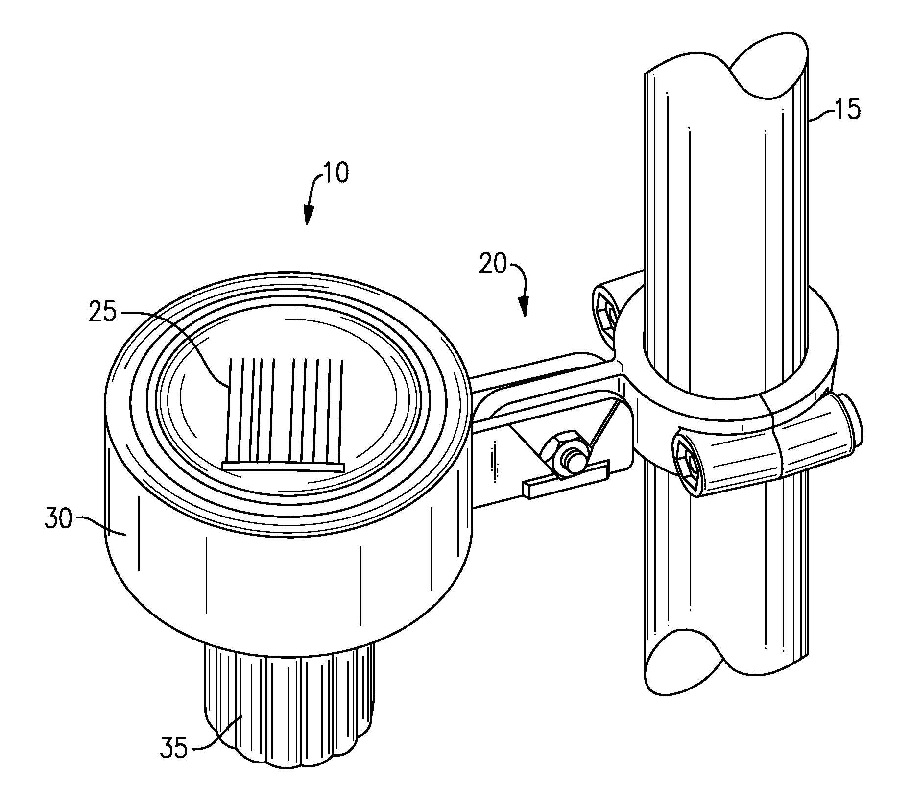
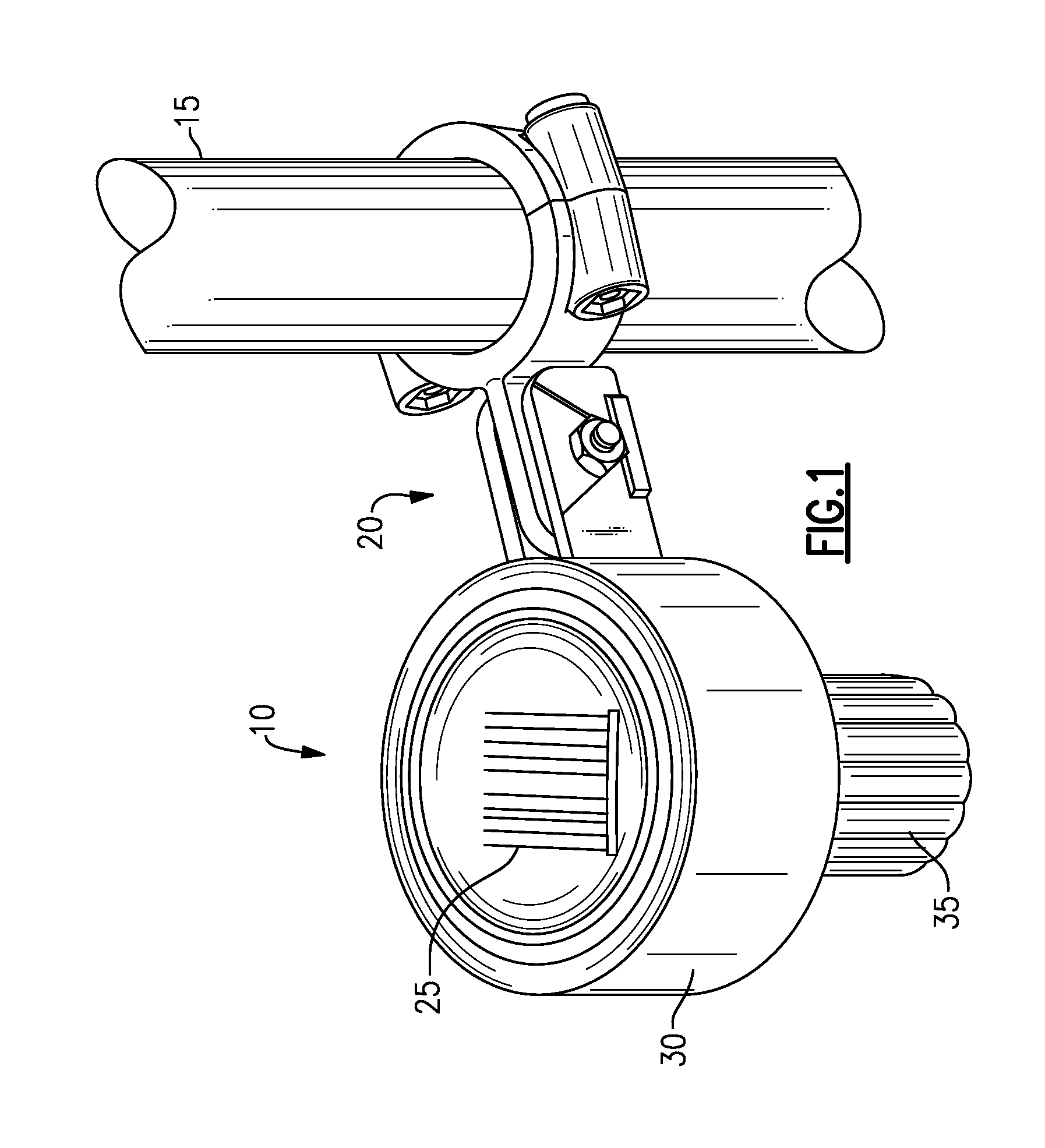
[0012]Referring now to FIG. 1, a light module 10 is mounted to a post 15 by a mount 20. The light module 10 has a solar cell 25, a body 30 and a lens 35. The post 15 may also be a mast, a spar, or a railing disposed on a floating object, such as a boat, or any other circular or shaped body that may be clamped and where light may be necessary.

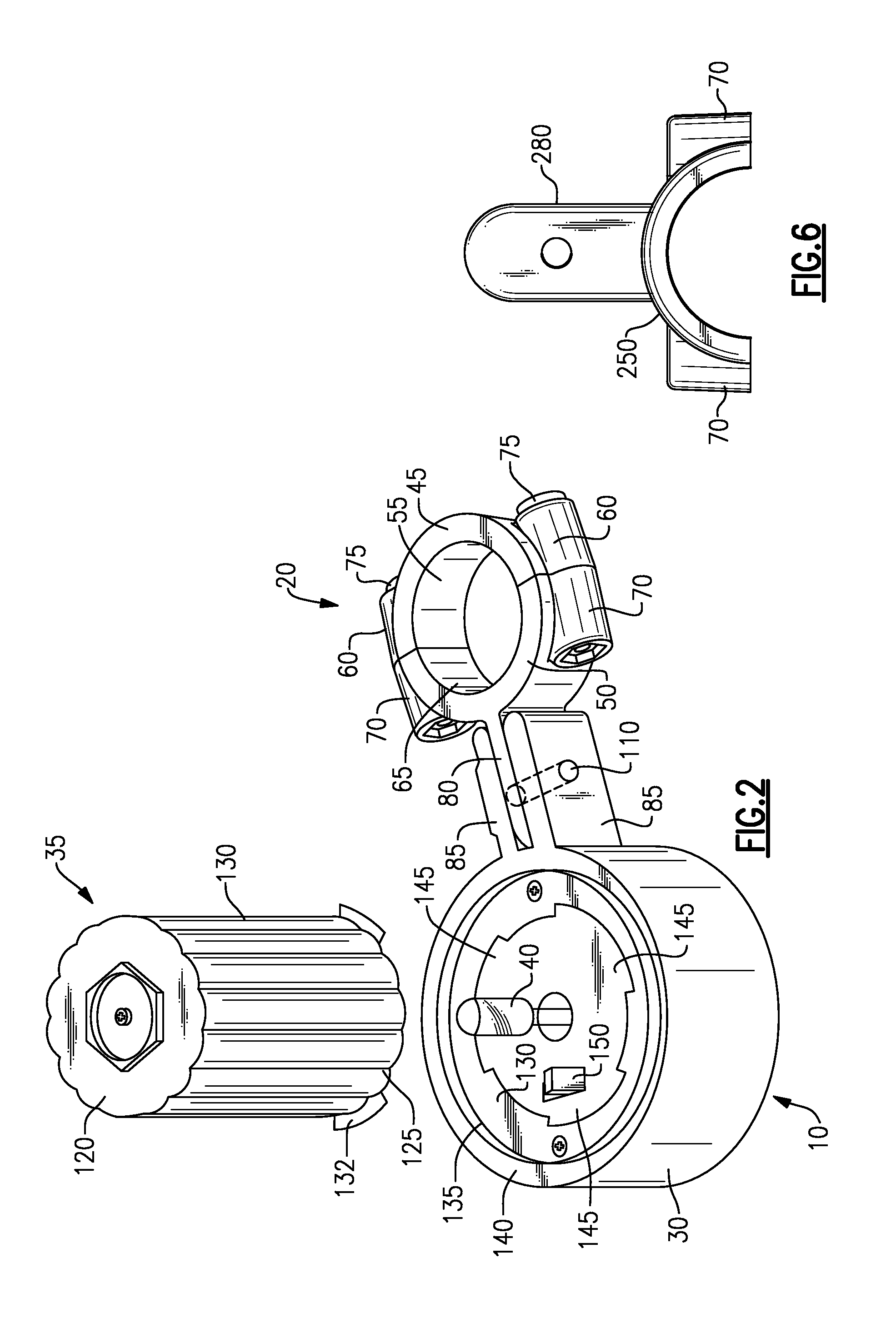
[0013]The body 30 contains the electronics (not shown) to store energy from the solar cell 25 and power a light source 40 (see FIG. 2), such as a bulb, an LED or the like when lighting is deemed necessary by user. The body 30 may include a battery (not shown), such as a disposable or rechargeable battery or a capacitor to store the sun's rays (not shown). The mount 20 has a first c-shaped clamp 45 and a second c-shaped clamp 50. The first clamp 45 has a semicircular section 55 with a pair of screw bodies 60 attached thereto. The second clamp half 50 has a semicircular portion 65, a pair of screw bodies 70 that mate with the screw bodies 60 of th...


PUM


Abstract

A light for use with a floating object, like a boat, has a body, the body having a flange and a light bulb extending therefrom, a lens, and a switch for activating and deactivating the bulb, the switch being disposed between the lens and the body. A mounting bracket attaches to the body and has an arm for cooperating with the flange such that the body may be disposed at varying angles relative to the arm, a first clamp attaching to the arm and a second clamp attaching to the first clamp such that the mounting bracket may be clamped to an item on the floating object.

Description

RELATED APPLICATION[0001]This application claims priority to U.S. Provisional Application Ser. No. 61 / 321,300, which was filed on Apr. 6, 2010.BACKGROUND OF THE INVENTION[0002]This application relates to lighting and more particularly to lighting for use in marine applications.[0003]Lighting is highly desirable for safely using and operating boats. Visibility to other craft is also particularly desirable. However, wiring for lighting is not necessarily desirable if the wires have to be placed through bulkheads where leaks may occur. Also, anything extra on boats requires maintenance.SUMMARY OF THE INVENTION[0004]According to an exemplar, a light for use with a floating object, like a boat, has a body, the body having a flange extending therefrom, a light bulb extending from the body, a lens, and a switch for activating and deactivating the bulb, the switch being disposed between the lens and the body. A mounting bracket attaches to the body and has an arm for cooperating with the fl...

Claims


Application Information

Patent Timeline
Patent Type & Authority Applications(United States)
IPC IPC(8): F21V5/00
CPCB60Q1/0483B63B45/00B63B2201/08F21Y2101/02F21V21/088F21V21/30F21W2101/04F21S9/037F21W2107/20F21Y2115/10
Inventor MITCHELL, BRIAN J.
Owner MITCHELL BRIAN J
Why Eureka
Try Eureka