
Switch with packet services processing

a technology of packet services and switches, applied in data switching networks, digital transmission, network topologies, etc., can solve the problems of increasing the routing and trip time of packets, and the number of dedicated appliances is necessary

Active Publication Date: 2011-10-06
AVAGO TECH INT SALES PTE LTD
View PDF9 Cites 14 Cited by
  • Summary
  • Abstract
  • Description
  • Claims
  • Application Information

AI Technical Summary

Benefits of technology

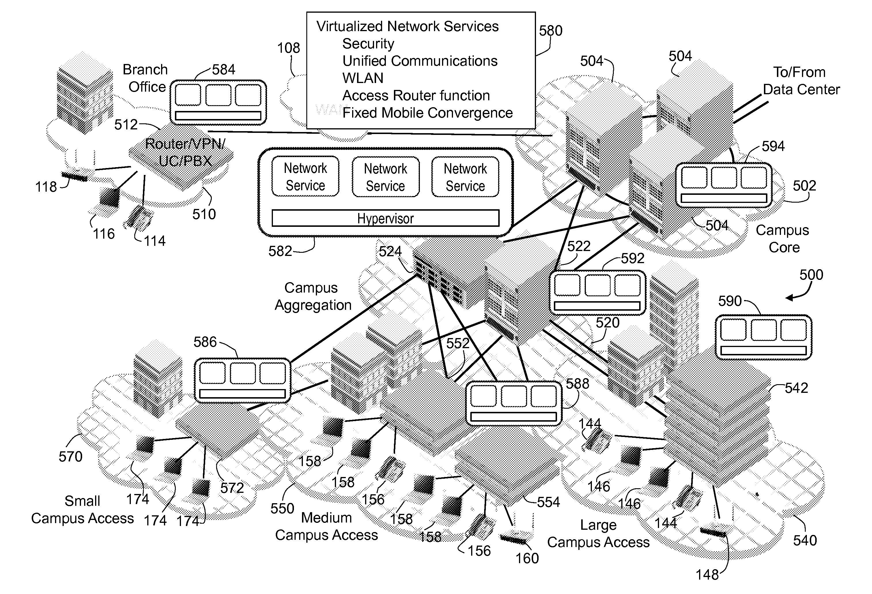
The present invention provides a way to offer network services through virtual machines running on switches in a network. This approach allows for efficient deployment of services at optimal locations in the network, rather than requiring dedicated appliances. The virtual machines can be executed on a single multi-core processor or on dedicated service processor boards. The packet processors in the switch ports analyze incoming packets and add a services tag containing services entries to any packets requiring available network services. Each switch reviews the services tag and performs any network services resident on that switch, removing the services entry for that service. This allows for easy deployment of network services using a graphical user interface and drag and drop operations. The management tool deploys the network services software, with virtual machines being instantiated on the switches as needed to support the network services.

Problems solved by technology

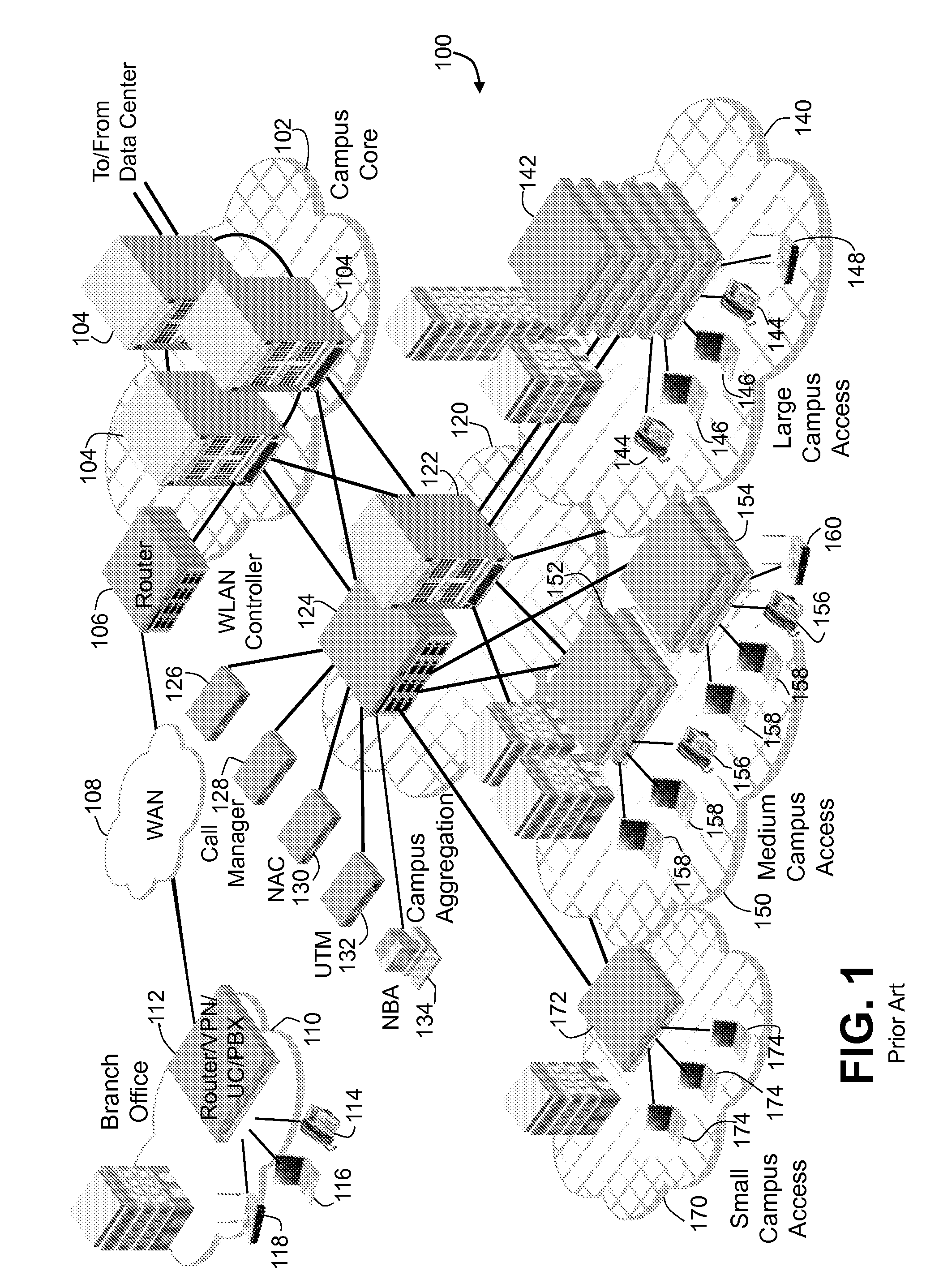
One problem that exists today in an enterprise environment is that a number of dedicated appliances are necessary to perform various network functions, such as wireless LAN control, unified communications, encryption and the like.
This is problematic because it represents additional devices to purchase and maintain and also increases routing and trip times for packets as they must traverse additional links.

Method used


Image

  • Switch with packet services processing
  • Switch with packet services processing
  • Switch with packet services processing

Examples


Embodiment Construction

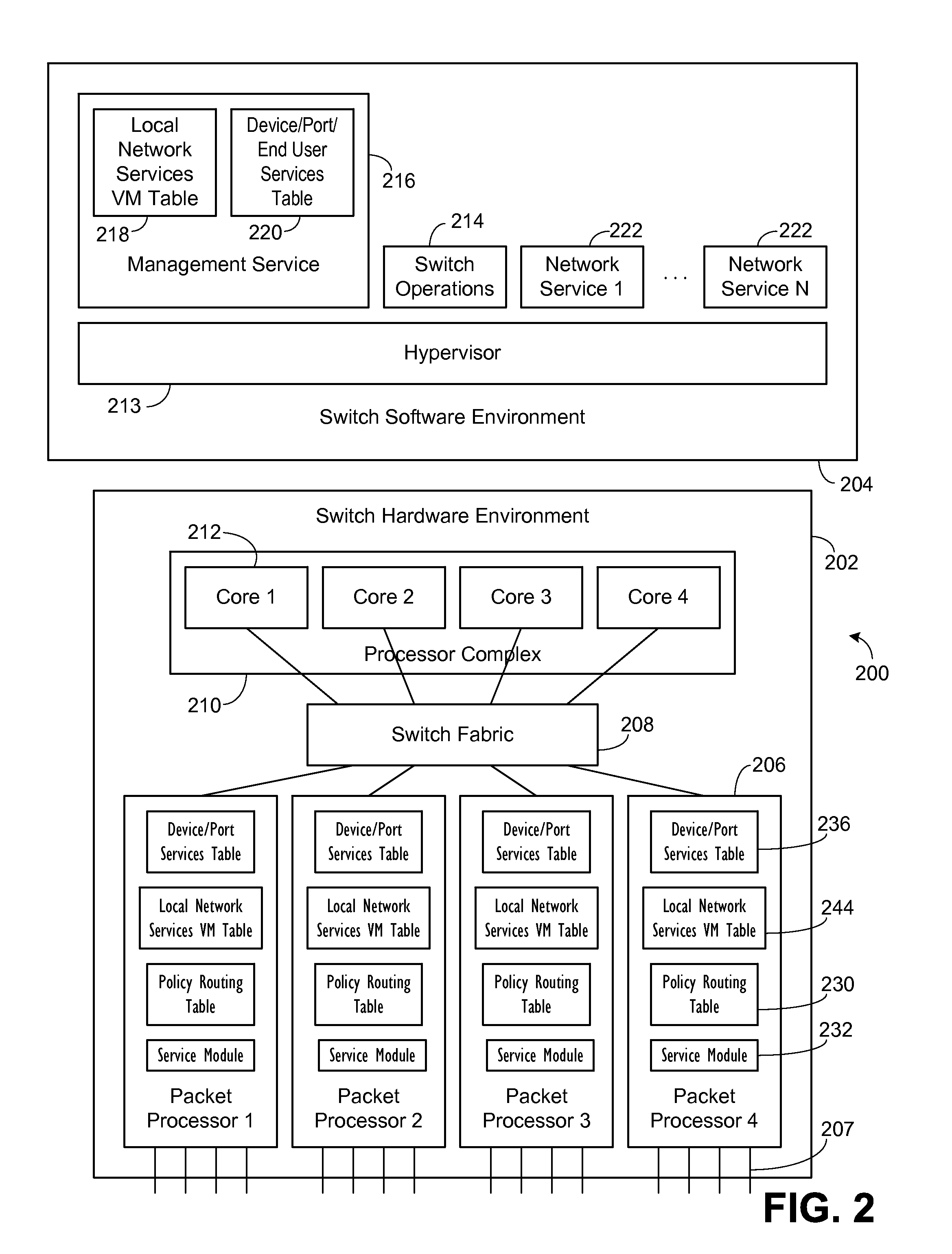
[0033]In embodiments according to the preferred invention, a conventional switch is utilized with software changes. For this invention, the term switches encompasses data traffic from Layers 1 through 7 in the conventional Open Systems Interconnection (OSI) model as defined by the International Organization for Standardization (ISO), along with the ITU-T. Two alternate embodiments are provided in FIGS. 2 and 3.

[0034]In the first embodiment of FIG. 2, a switch 200 is illustrated as having hardware 202 and software 204 environments. Discussing first the hardware environment 202, a plurality of packet processors 206 are illustrated. The packet processors 206 include a plurality of network ports 207 for receiving network communications. The packet processors 206 are connected to a switch fabric 208. The switch fabric 208 provides the basic switching operations for the switch 200. A processor complex 210 is connected to the switch fabric 208. The processor complex 210 in the embodiment i...


PUM


Abstract

Virtual machine environments are provided in the switches that form a network, with the virtual machines executing network services previously performed by dedicated appliances. The virtual machines can be executed on a single multi-core processor in combination with normal switch functions or on dedicated services processor boards. Packet processors analyze incoming packets and add a services tag containing services entries to any packets. Each switch reviews the services tag and performs any network services resident on that switch. This allows services to be deployed at the optimal locations in the network. The network services may be deployed by use of drag and drop operations. A topology view is presented, along with network services that may be deployed. Services may be selected and dragged to a single switch or multiple switches. The management tool deploys the network services software, with virtual machines being instantiated on the switches as needed.

Description

CROSS REFERENCE TO RELATED APPLICATIONS[0001]This application claims the benefit under 35 U.S.C. §119(e) of U.S. Provisional Patent Applications Ser. Nos. 61 / 319,348, entitled “NETWORK SWITCHES WITH VIRTUAL MACHINES AND SIMPLIFIED DISTRIBUTION,” filed Mar. 31, 2010 and 61 / 325,040, entitled “NETWORK SWITCHES WITH VIRTUAL MACHINES AND SIMPLIFIED DISTRIBUTION,” filed Apr. 16, 2010, which are hereby incorporated by reference.[0002]This application is related to U.S. Patent Applications Serial Nos. ______, entitled “Simplified Distribution of Software to Networked Devices”; ______, entitled “Ingress and Egress Switch which Determines Services Related to an Incoming Packet”; and ______, entitled “Network Architecture with Distribution of Packet Services to Various Switches”, all by the current inventors and filed on the same date as the current application and all of which are hereby incorporated by reference.BACKGROUND OF THE INVENTION[0003]1. Field of the Invention[0004]The invention re...

Claims


Application Information

Patent Timeline
Patent Type & Authority Applications(United States)
IPC IPC(8): H04L12/56H04L45/60H04L45/74
CPCH04L41/5041H04L49/70H04L49/355H04L43/18H04L41/40H04L45/745H04W84/12H04W88/08H04L45/021H04L45/56H04L69/22H04L45/74H04L49/354
Inventor KWON, JAMESAMMIRATO, JOSEPH
Owner AVAGO TECH INT SALES PTE LTD
Learn More