
Plunger pin shackle locking apparatus

a technology of locking apparatus and shackle, which is applied in the direction of eye fasteners, hook fasteners, fastening means, etc., can solve the problems of sailboat malfunction, violent flogging, and accidental opening of shackle pins

Inactive Publication Date: 2011-10-13
TYLASKA TIMOTHY T +1
View PDF10 Cites 11 Cited by
  • Summary
  • Abstract
  • Description
  • Claims
  • Application Information

AI Technical Summary

Benefits of technology

[0006]It is an aspect of the invention to provide a plunger pin snap shackle with a lock which prevents the accidental release of the snap shackle under heavy flogging during windy conditions or snagging.
[0007]Another aspect on the invention is to provide a plunger snap shackle with a lock that can exist at two “at-rest” states; one which prevents significant translation of the plunger pin and one which allows free translation of the plunger pin over a range sufficient to release the latch.
[0008]Yet another aspect of the invention is to provide a plunger pin snap shackle with a lock that can easily and quickly be engaged and disengaged by the operator.
[0009]Another aspect of the invention is to provide a plunger pin snap shackle with a lock wherein the locking mechanism itself has a configuration that does not create an additional snagging hazard.

Problems solved by technology

There are numerous situations, particularly in sailing, when a snap shackle may accidentally open.
Massive accelerations that occur when the sails and attached rigging experience flogging can sometimes cause a plunger pin to accidentally open due to inertial forces that overcome the resistive forces of the plunger spring.
Frequently, these shackles are attached to ropes and sails that, as noted above, can experience violent flogging in windy conditions.
Under these conditions the shackle can sometimes release unintentionally, resulting in a malfunction of the sailboat and possible loss of equipment or injury to the crew.

Method used


Image

  • Plunger pin shackle locking apparatus
  • Plunger pin shackle locking apparatus
  • Plunger pin shackle locking apparatus

Examples


Embodiment Construction

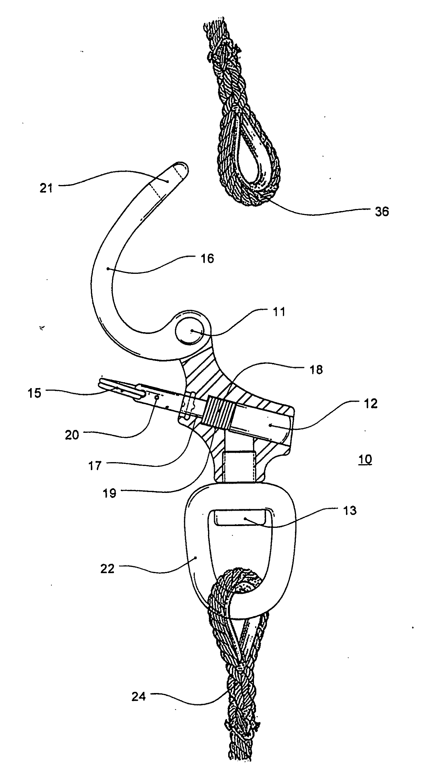
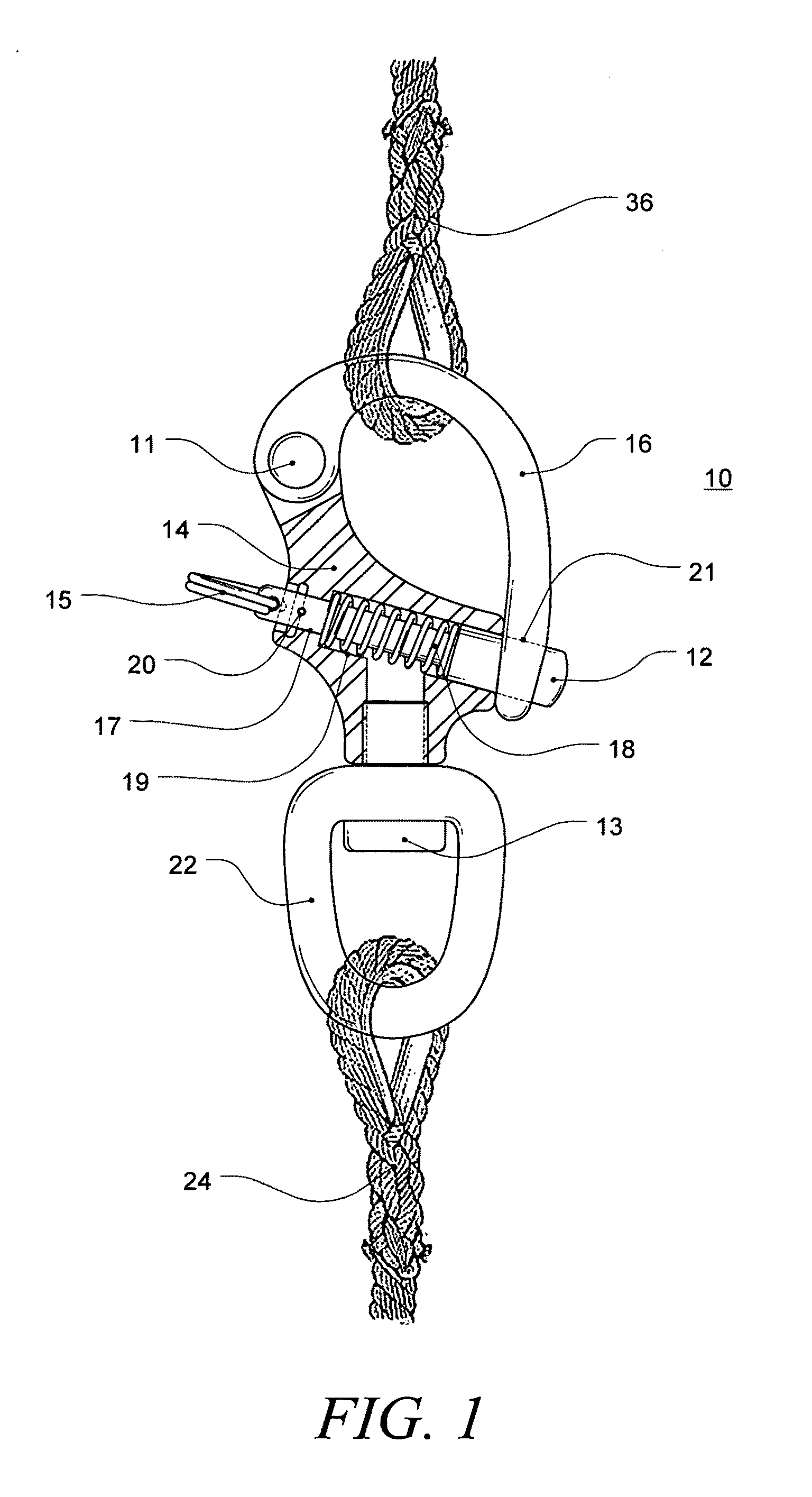
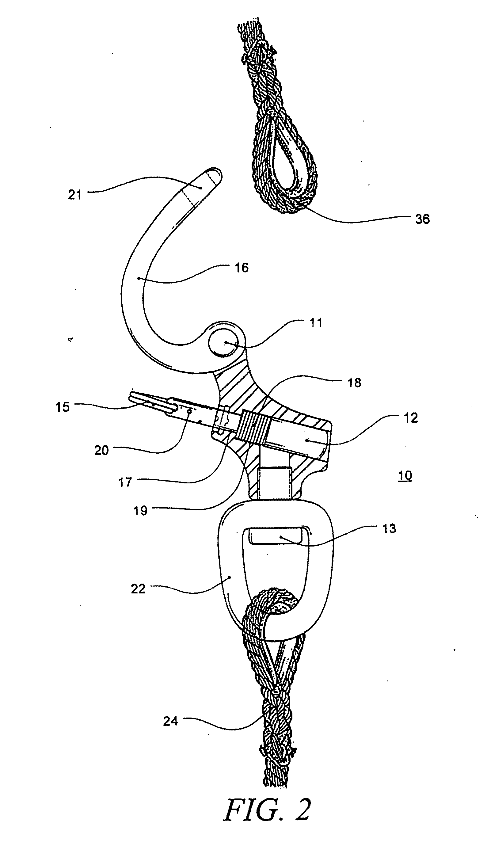
[0017]The most basic configuration of the locking plunger pin snap shackle according to the invention comprises a plunger pin, a lock pin, a spring, a main body, a hook and a bail. This configuration, as shown in FIG. 1 and further detailed in FIGS. 2-8, is suitable for pull pin style sailing snap shackles. Variations in size and shape in accordance with the mechanism may be necessary for different applications.

[0018]The locking plunger pin snap shackle 10 connects together members 24 and 36, in this case, lines with a thimble spliced therein. The shackle 10 comprises a main body 14, a pivot pin 11, a hook 16, a lock pin 20, a spring 18, a plunger pin 12, a snap ring 15, a threaded or welded stud 13 and a bail 22. Plunger pin 12 is inserted into bores 17 and 19 of main body 14 and bore 21 of hook 16 against spring 18, which is also inserted into main body 14. Plunger pin 12 is held captive in main body 14 by lock pin 20. Bail 22 is attached to main body 14 with threaded or welded st...


PUM


Abstract

A plunger pin schackle locking apparatus that prevents accidental release of the snap shackle under heavy flogging during windy conditions or snagging. Two “at-rest” states or positions are provided. This first one prevents significant translation of the plunger pin such that apparatus remains closed and locked. The second one allows free translation of the plunger pin over a range sufficient to release the latch. The locking mechanism does not significantly change the overall configuration, size and relative dimensions of a similarly rated but non-locking equivalent plunger pin snap shackle to allow for interchangeability.

Description

[0001]This application claims benefit of U.S. Provisional Application Ser. No. 61 / 341,939 filed Apr. 7, 2010 pursuant to 35 USC §119(e).FIELD OF THE INVENTION[0002]This invention relates to fasteners, in particular, to shackles used for joining two members together.BACKGROUND OF THE INVENTION[0003]Plunger pin snap shackles are most commonly used in sailing but are used in a variety of applications where it is desirable to join and disjoin two members with relative ease. There are numerous situations, particularly in sailing, when a snap shackle may accidentally open. Massive accelerations that occur when the sails and attached rigging experience flogging can sometimes cause a plunger pin to accidentally open due to inertial forces that overcome the resistive forces of the plunger spring. Snagging of the plunger pin sometimes also occurs when the shackle is dragged across the deck or hoisted up the mast. For these applications, it is desirable to have a locking mechanism that holds t...

Claims


Application Information

Patent Timeline
Patent Type & Authority Applications(United States)
IPC IPC(8): F16B45/02
CPCY10T24/45435F16B45/02F16B45/045F16B45/029F16B45/034
Inventor TYLASKA, TIMOTHY T.DIXON, THOMAS W.
Owner TYLASKA TIMOTHY T
Learn More