Cable support block

a technology of support block and cable, which is applied in the field of cable, can solve the problems of not substantially symmetrical relative to a vertical plane, the closure arm cannot allow quick and easy access of new cables onto the supporting roller, and the manipulation of cable support block becomes more complex for temporarily installing, etc., to achieve the effect of easy and secure engagement and disengagemen

Inactive Publication Date: 2001-11-13
ELECTRO SAGUENAY
View PDF20 Cites 35 Cited by
  • Summary
  • Abstract
  • Description
  • Claims
  • Application Information

AI Technical Summary

Benefits of technology

It is the gist of the present invention to provide a cable support block that allows a new cable being installed and possibly stringed to be temporarily su

Problems solved by technology

A first disadvantage of the cable support block of the Castilano patent is that it is not substantially symmetrical relative to a vertical plane coinciding with the support strand.
This assymmetrical configuration is not desirable, since the cable support block may be prone to tilt laterally under its own weight, especially if it is not loaded with the new cable, and thus manipulation of the cable support block becomes more complex for temporarily installing thereon the new cable.
The main disadvantage of the cable support block of the Castilano patent is that the closure arm does not allow quick and easy access of the new cable onto the supporting roller.
This can become a tedious and time consuming operation, especially in areas where there is irregular terrain under the cables which requires vehicles equipped with aerial baskets to move at a slower pace.
Moreover, this operation at cable height can become hazarardous to the workperson, since he will come in close proximity with the upper strand, which can be a power conducting line.
When such a case occurs, serious physical injury to the workperson can occur if he gets electrocuted.
Also, the person operating high above ground le

Method used


Image

  • Cable support block
  • Cable support block
  • Cable support block

Examples


Embodiment Construction

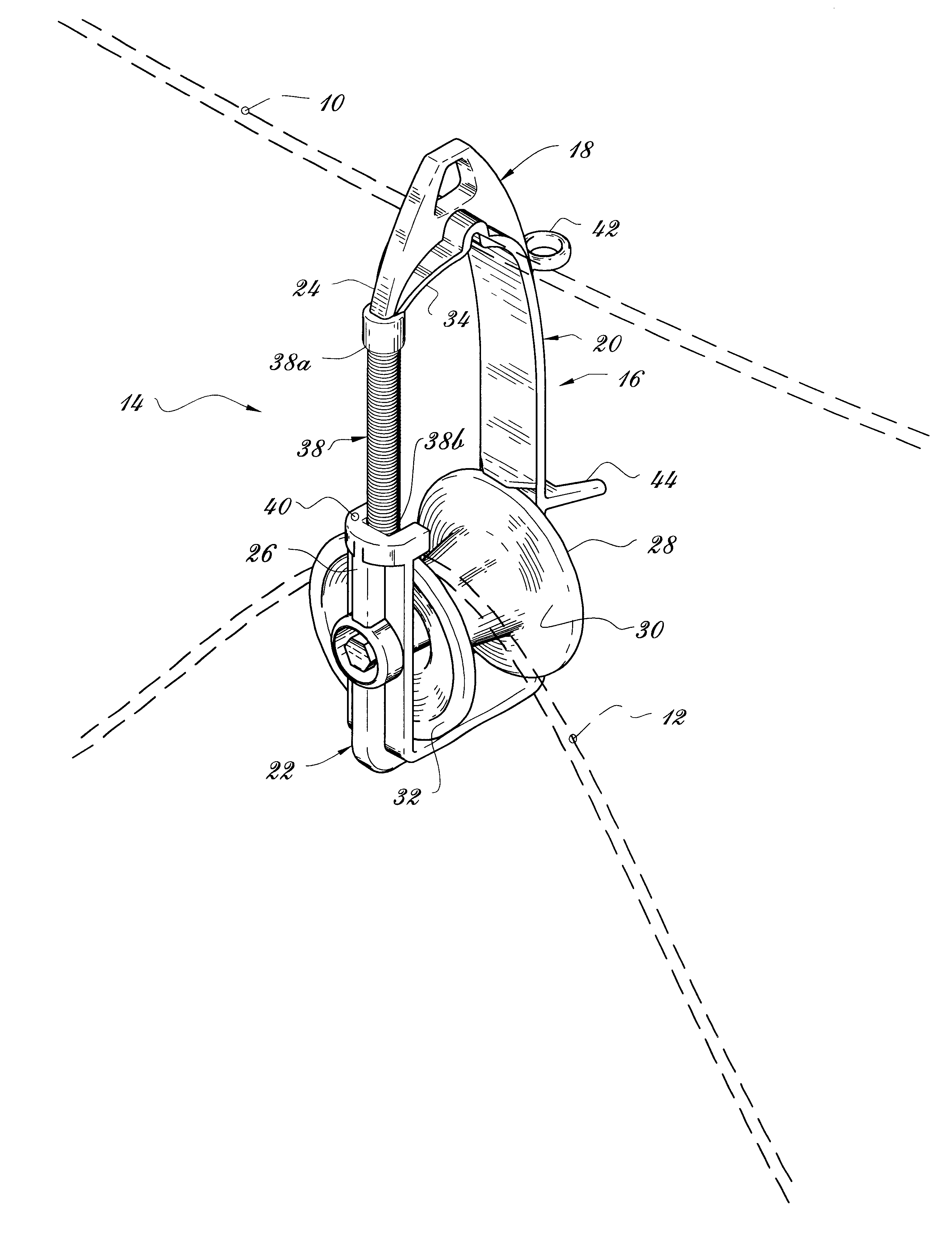
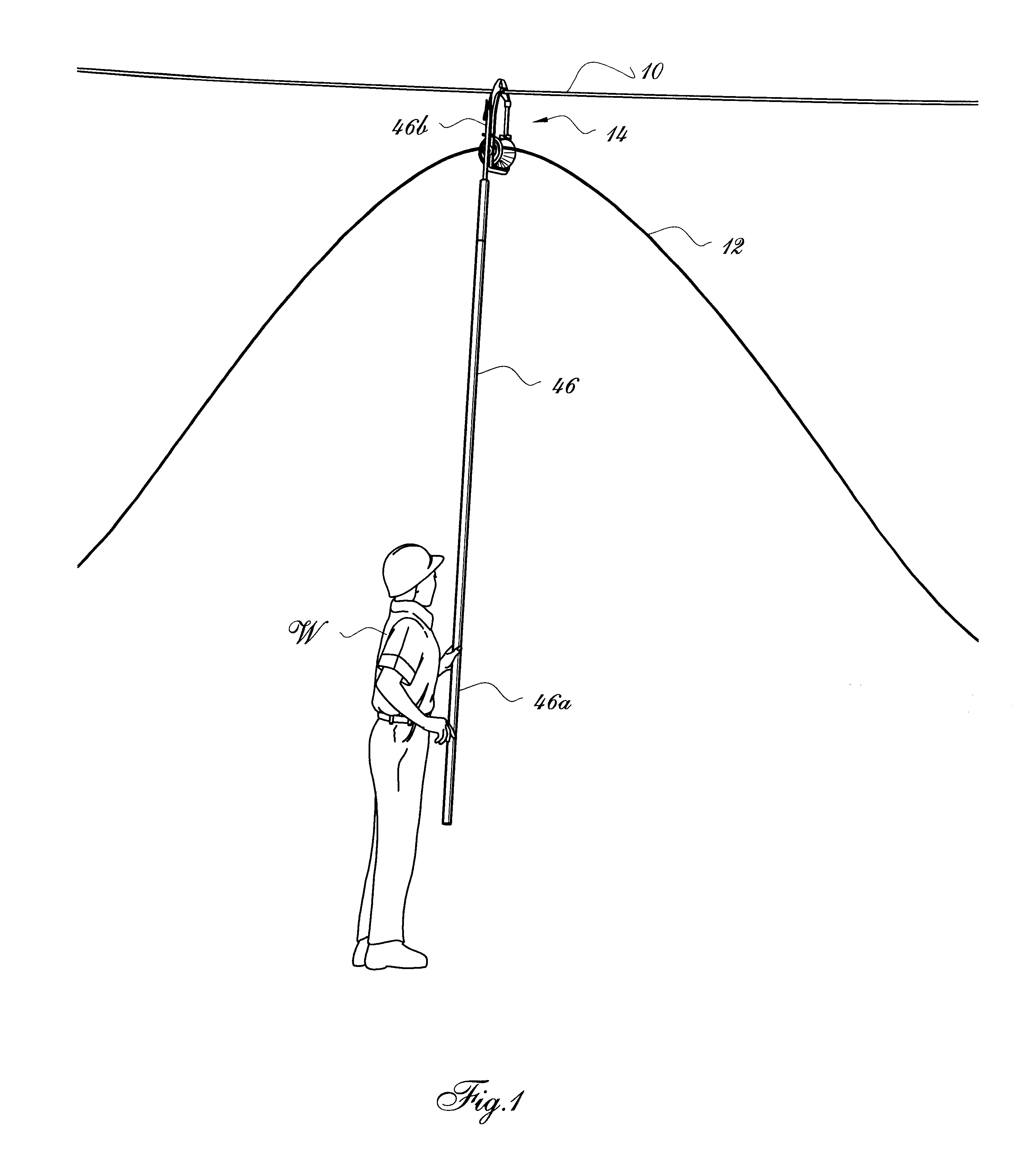
FIG. 1 shows an upper cable 10 fixedly attached to spaced-apart upright support posts (not shown), with the upper cable 10 thus being spacedly supported over ground in a conventional manner. A lower cable 12 to be installed and possibly stringed is to be supported temporarily under the upper cable by a number of cable support blocks 14 according to the invention, until the final attachment to the posts can be accomplished when the stringing operation is completed, and when the lower cable 12 is ready to be suitably tensioned between the posts, as known in the art. Although the present invention is particularly designed for use with power conducting cables or telecommunication cables, it is understood that it is not restricted to such use, and that cables of any suitable nature may be supported with cable support blocks such as block 14.

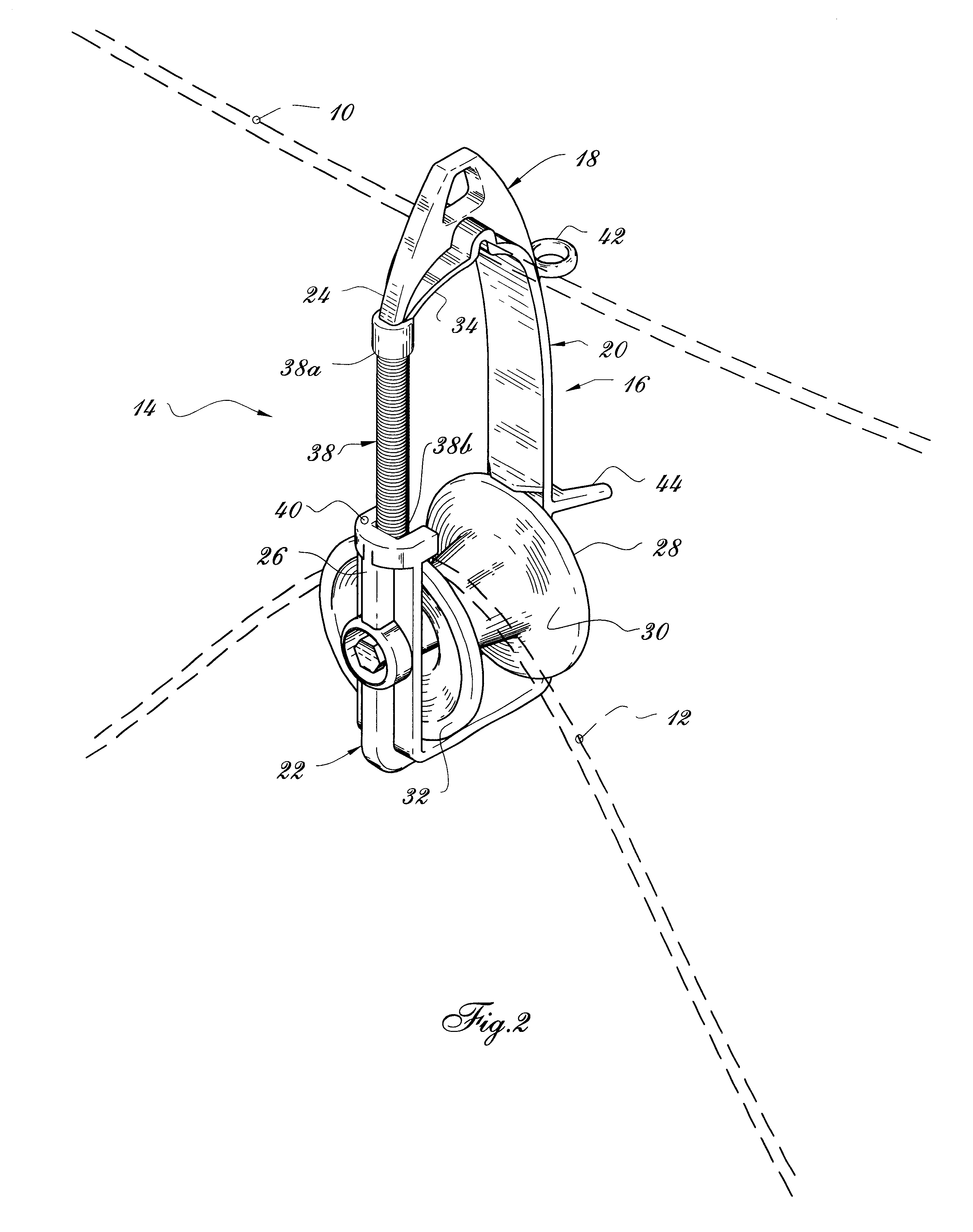
As shown in FIGS. 2 and 3, cable support block 14 comprises an arcuate elongated rigid substnatially planar frame 16 defining an upper portion 18, an...


PUM


Abstract

The cable support block is for temporarily supporting a lower cable to an upper aerial cable. The support block comprises a rigid arcuate frame having an upper yoke straddling the upper cable, and an idle load-bearing roller rotatably mounted on the frame and supporting the lower cable. An elongated coil spring is fixedly attached at a first end thereof to the frame and defines a second opposite free end portion thereof movable relative to the first end by resilient: deformation of the coil spring. To insert a cable into the arcuate frame, the cable is forcibly abutted against the coil spring which will resiliently yield to allow access of the cable into the arcuate frame by being inwardly deformed.

Description

The present invention relates to cables such as power conducting or telecommunication cables, and more particularly to a support block supported on a suspended cable, for installing and / or stringing a new cable supported by the support block.It is known to provide cable support blocks for temporarily supporting power conducting or telecommunication cables or the like, while stringing the cable and installing same. A number of support blocks are temporarily installed on a suspended cable during the stringing / installation operations of a new cable supported by the support blocks, and are to be removed afterwards, once the new cable is permanently attached to the upright cable support posts which are driven in the ground. Thus, a support block allowing easy and quick installation and removal thereof is an asset.U.S. Pat. No. 4,549,723 issued in 1985 to C. R. Castilano discloses a cable support block which comprises a rigid bracket which can be hooked onto an upper support strand which ...

Claims


Application Information

Patent Timeline
IPC IPC(8): B66D3/00B66D3/04H02G1/04
CPCB66D3/046H02G1/04
Inventor FLEURY, REJEANFLEURY, JOCELYNFLEURY, JEAN-PIERRE
Owner ELECTRO SAGUENAY
Why Eureka
Try Eureka