IOL injector device and method

a technology of injector device and iol, which is applied in the field of ophthalmic surgical devices and methods, can solve the problems of high care required in the handling of iol, trauma to the surrounding tissues of the eye, and high undesirable surgical outcomes, and achieves the effects of reliable loading, good visualization and protection of iol in the loading chamber, and compressing and delivering iol therethrough

Inactive Publication Date: 2005-07-07
BAUSCH & LOMB INC
View PDF16 Cites 31 Cited by
  • Summary
  • Abstract
  • Description
  • Claims
  • Application Information

AI Technical Summary

Benefits of technology

[0007] The present invention provides an injector device which enables the reliable loading, compressing and delivery of an IOL therethrough. More particularly, the invention provides an injector device for delivering an IOL into an eye wherein the injector device includes a compressor mechanism for compressing the IOL, the compressor including one or more catch and detents provided on facing surfaces thereof so as to prevent the compressor from inadvertently releasing from the injector device. The catch and detent pairs are positioned laterally of the IOL loading chamber such that good visualization and protection of the IOL in the loading chamber is maintained throughout the IOL compression step. In an advantageous embodiment, two pairs of catch and detent pairs are provided in spaced relation to enable sequential advancement and locking of the compressor with respect to the IOL loading chamber.

Problems solved by technology

Since IOLs are very small and delicate articles of manufacture, great care must be taken in their handling.
Should the IOL be damaged during delivery into the eye, the surgeon will most likely need to extract the damaged IOL from the eye and replace it with a new IOL, a highly undesirable surgical outcome.
Should the IOL be expelled from the tip too quickly or in the wrong orientation, the surgeon must further manipulate the IOL in the eye which could result in trauma to the surrounding tissues of the eye.
Due to the delicate nature of the IOL, there is a risk that the nurse and / or surgeon will inadvertently damage the IOL during the loading and compressing steps resulting in a failed implantation.

Method used


Image

  • IOL injector device and method
  • IOL injector device and method
  • IOL injector device and method

Examples


Embodiment Construction

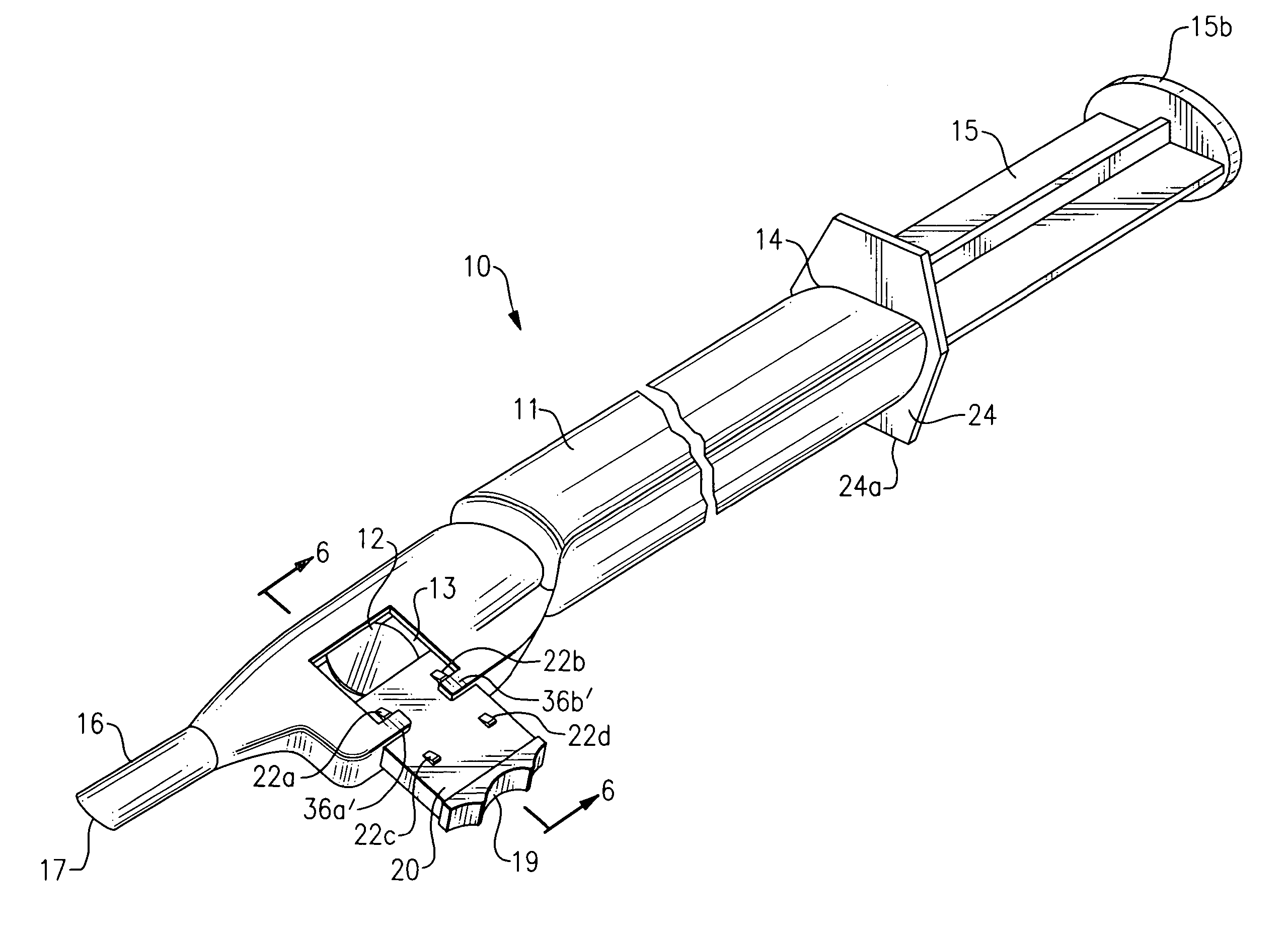
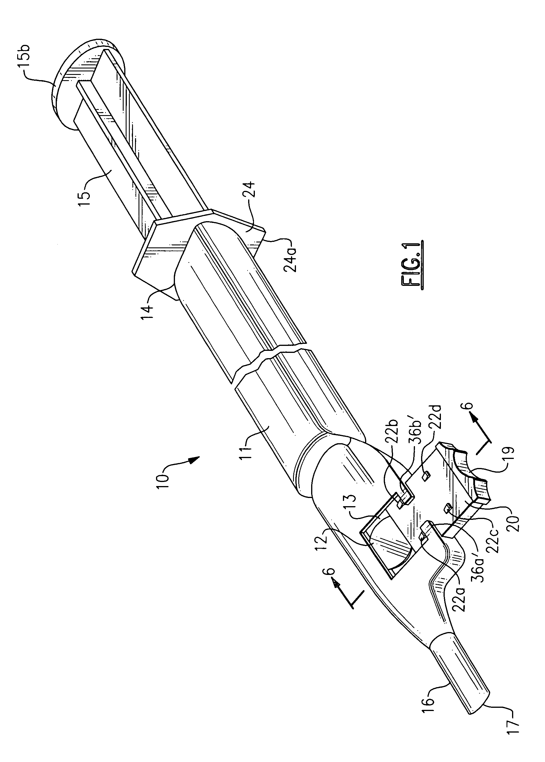
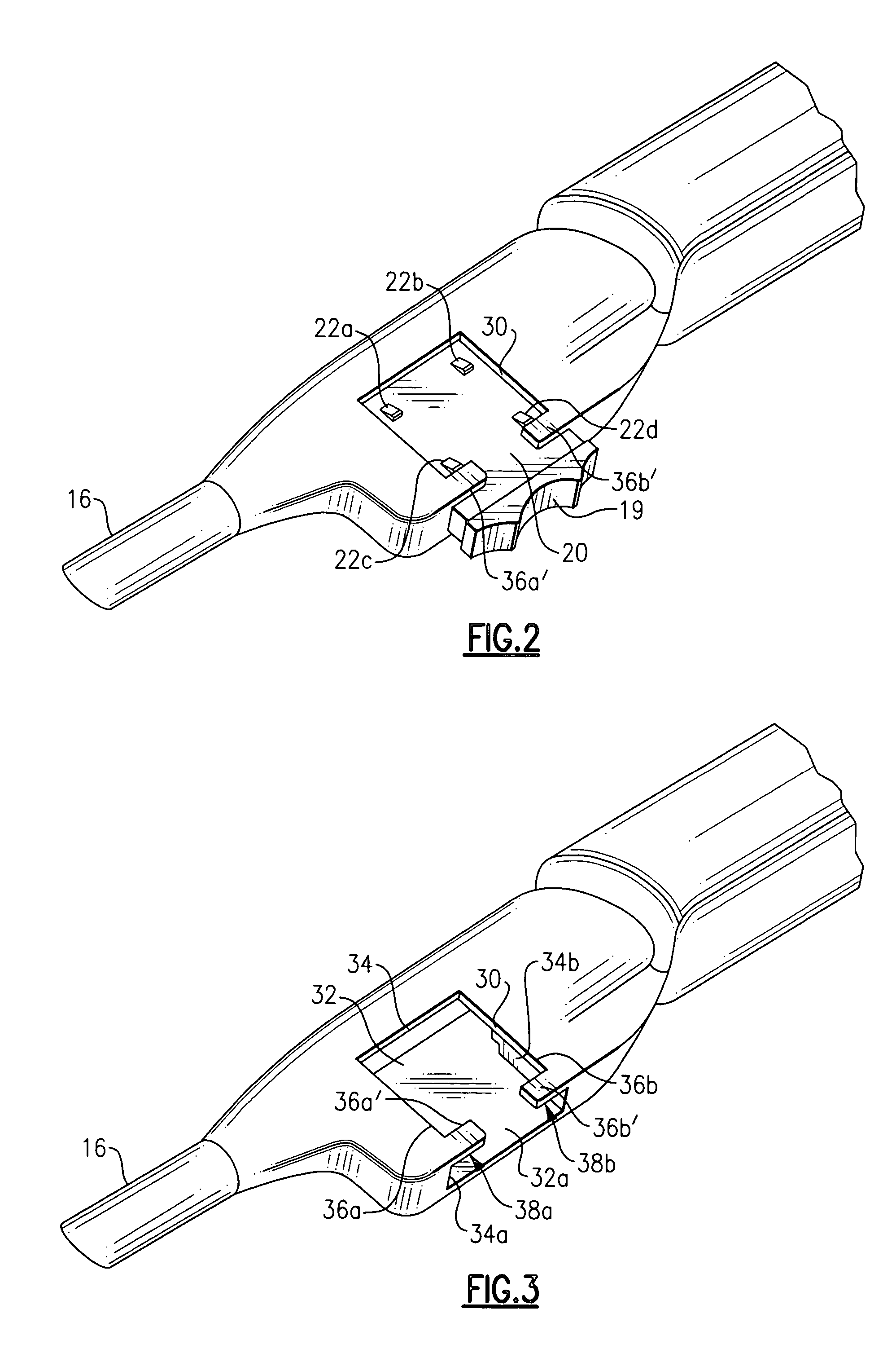
[0015] Referring now to the drawing, there is seen in FIG. 1 an injector device denoted generally by the reference numeral 10. Injector device 10 is used to compress and deliver an IOL 12 into an eye (not shown). The injector 10 is generally of the construction shown and described in commonly assigned U.S. Pat. No. 5,944,725, the entire disclosure of which is incorporated by reference. The present invention provides a different locking position for the compressor denoted 40 in the '725 patent and numeral 20 in the instant application figures. The principle advantage of the present invention over the '725 device is that the locking mechanism is no longer positioned adjacent the loaded IOL when the compressor is in the fully closed position. This feature eliminates the possibility of the locking mechanism coming into contact with the loaded IOL which could damage the IOL. Further, by having the locking mechanism positioned laterally of the longitudinal passageway and particularly the ...


PUM


Abstract

Improved closing and locking mechanism for an IOL compressor component of an IOL injector device includes two equally spaced, sequential pairs of catches provided on a wall of the compressor for sequentially engaging with a respective pair of detents formed adjacent the compressor opening of the injector body as the compressor is moved to the closed position.

Description

BACKGROUND OF THE INVENTION [0001] The present invention relates to ophthalmic surgical devices and methods. More particularly, the present invention relates to a device and method for inserting an intraocular lens (IOL) into an eye. [0002] IOLs are artificial lenses used to replace the natural crystalline lens of the eye when the natural lens has cataracts or is otherwise diseased. IOLs are also sometimes implanted into an eye to correct refractive errors of the eye in which case the natural lens may remain in the eye together with the implanted IOL. The IOL may be placed in either the posterior chamber or anterior chamber of the eye. IOLs come in a variety of configurations and materials. Some common IOL styles include the so-called open-looped haptics which include the three-piece type having an optic and two haptics attached to and extending from the optic; the one-piece type wherein the optic and haptics are integrally formed (e.g., by machining the optic and haptics together f...

Claims


Application Information

Patent Timeline
Patent Type & Authority Applications(United States)
IPC IPC(8): A61F2/16
CPCA61F2/1664
Inventor RATHERT, BRIAN D.
Owner BAUSCH & LOMB INC
Why Eureka
Try Eureka