Fuel cell stack

a fuel cell and stacking technology, applied in the field of fuel cell stacks, can solve the problems of excessively large load on the curved portion, undesirable deformation of the bottom of the casing, and inability to so as to reduce the thickness and weight of the casing, prevent deformation, and reliably support the load of the stack body

Active Publication Date: 2010-06-10
HONDA MOTOR CO LTD
View PDF3 Cites 6 Cited by
  • Summary
  • Abstract
  • Description
  • Claims
  • Application Information

AI Technical Summary

Benefits of technology

[0010]The present invention has been made to solve the problem of this type, and an object of the present invention is to provide a fuel cell stack which makes it possible to achieve reduction in the thickness and the weight of a casing, and reliably support the load of a stack body to suitably prevent deformation.
[0013]In the present invention, the load of the stack body is supported by a relatively low ridge provided integrally with the bottom plate member of the casing. By the reinforcement member bridging the recess, which corresponds to the back surface of the ridge, deformation in a direction to open the ridge is prevented. In the structure, reduction in the thickness and the cost of the casing itself is achieved. Further, it becomes possible to improve the rigidity in cross section, the flexural elasticity, and the shearing reaction force, and thus, obtain the lightweight casing having high rigidity. Further, the height of the ridge is reduced effectively, and the overall height of the casing is reduced as much as possible.

Problems solved by technology

Under the circumstances, the stack body formed by stacking a large number of unit cells is considerably heavy.
Therefore, since an excessively large load of the stack body is applied to the bottom of the casing, the bottom of the casing may be deformed undesirably.
In particular, an excessively large load tends to be applied to the curved portion 4.

Method used


Image

  • Fuel cell stack
  • Fuel cell stack
  • Fuel cell stack

Examples


first embodiment

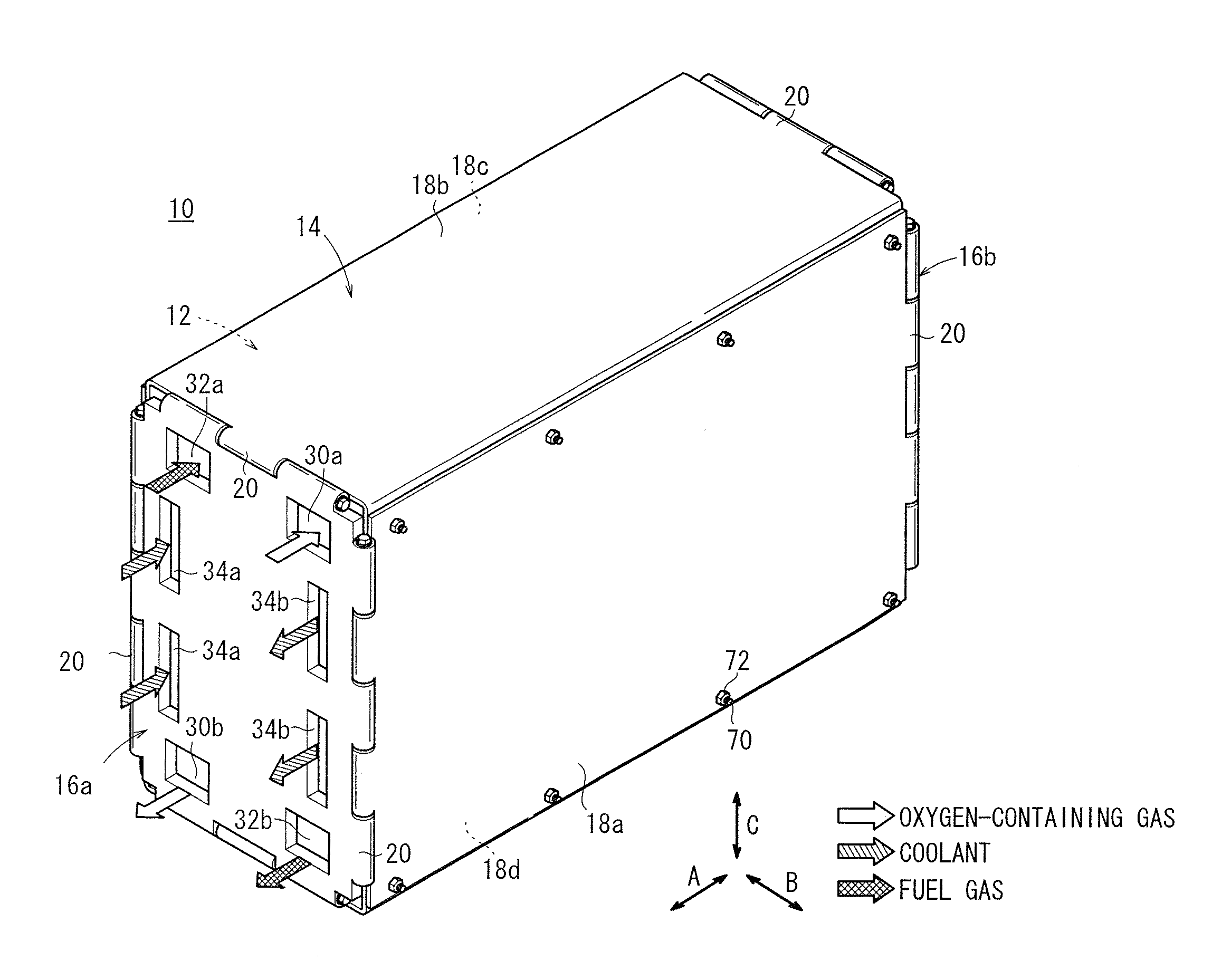
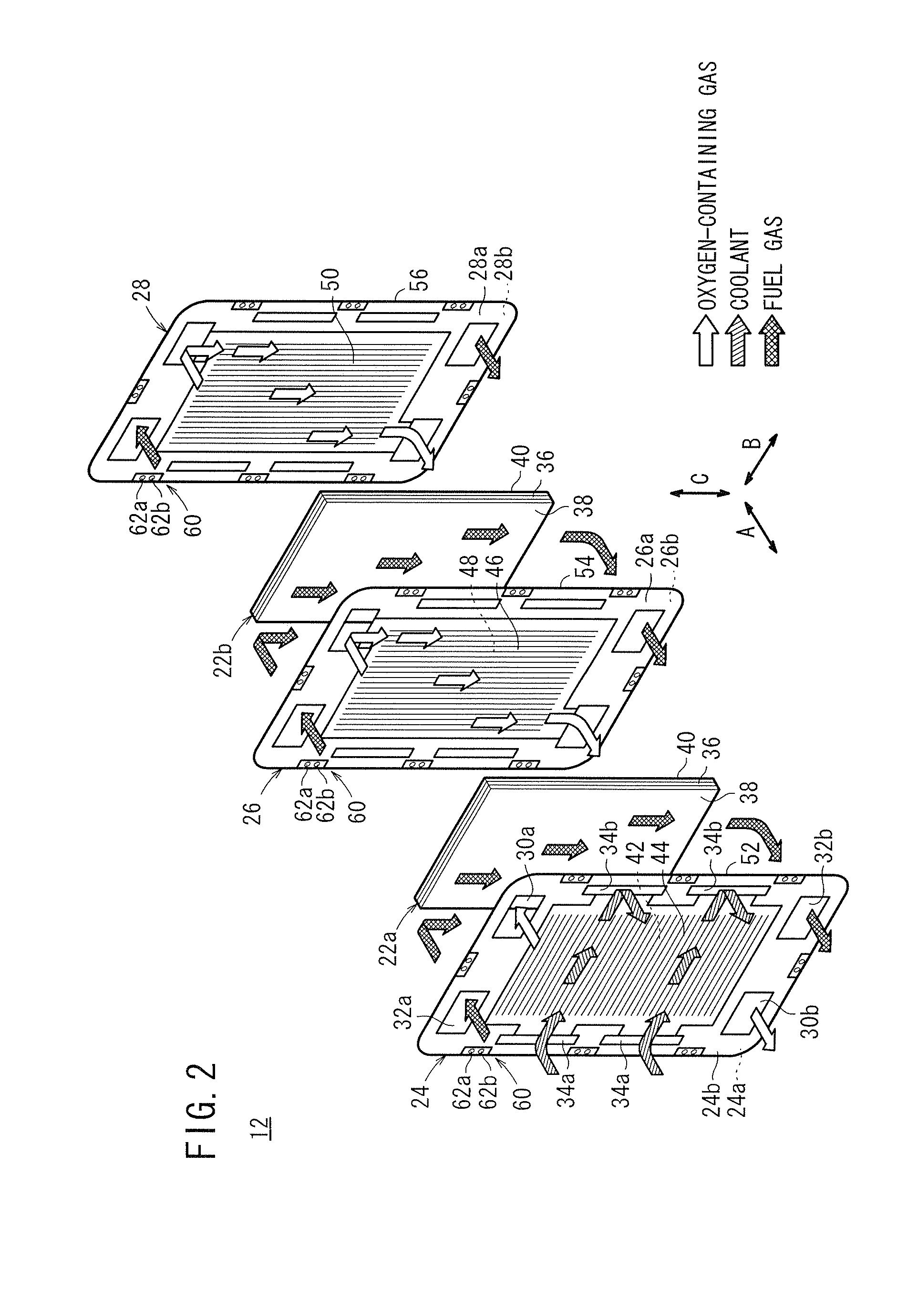
[0032]FIG. 1 shows a fuel cell stack 10 according to the present invention. For example, the fuel cell stack 10 is mounted in a vehicle. The fuel cell stack 10 includes a plurality of fuel cell units (unit cells) 12 stacked together in a direction indicated by an arrow A and a box-shaped casing 14 containing the fuel cell units 12. The casing 14 includes end plates 16a, 16b provided at opposite ends of the fuel cell units 12 in the stacking direction, four side panels 18a to 18d provided on sides of the fuel cell units 12, and hinge mechanisms 20 for coupling the end plates 16a, 16b and the side panels 18a to 18d together. The side panels 18a to 18d are made of stainless steel (e.g., SUS 304) or other metal material, or carbon material.

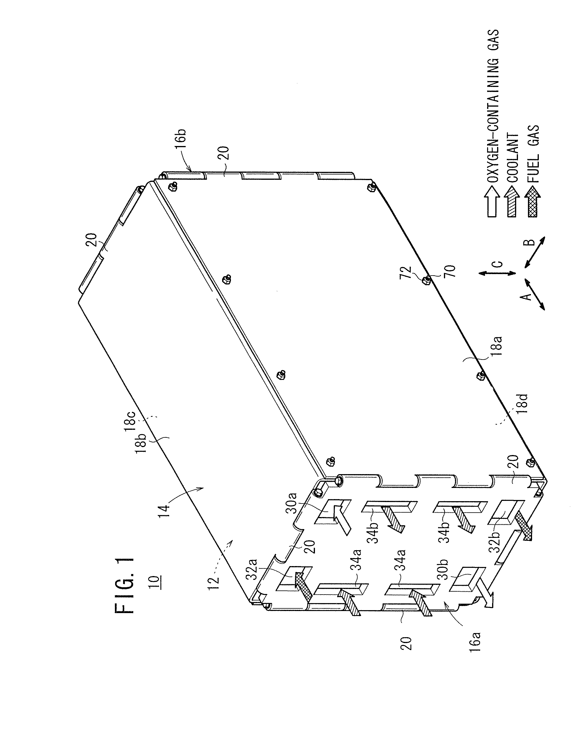
[0033]As shown in FIG. 2, the fuel cell unit 12 includes a first membrane (electrolyte) electrode assembly (MEA) 22a, a second membrane electrode assembly (MEA) 22b, a first separator 24, a second separator 26, and a third separator 28. The first memb...

third embodiment

[0065]FIG. 8 is a partial exploded perspective view of a fuel cell stack 90 according to the preset invention.

[0066]In the fuel cell stack 90, a reinforcement plate (reinforcement member) 92 is provided on the side panel 18d of the casing 14. The reinforcement plate 92 is a plate having narrow portions 92a at both ends in the direction indicated by the arrow A. Further, holes 92b are formed in the respective narrow portions 92a for weight reduction.

[0067]The reinforcement plate 92 is fixed to the side panel 18d at a plurality of welding points 94. As shown in FIG. 9, a predetermined number of the welding points 94 are formed in each of both sides of the recess 64a. Specifically, the welding points 94 are arranged in one line on each side of both end portions in the direction indicated by the arrow A, and the welding points 94 are arranged in two lines on each side of the center portion in the direction indicated by the arrow A. A drainage hole 96 is provided at substantially the cen...

fourth embodiment

[0071]FIG. 10 is a bottom view showing a fuel cell stack 100 according to the present invention.

[0072]The fuel cell stack 100 includes a reinforcement plate (reinforcement member) 102 fixed to the side panel 18d of the casing 14. The reinforcement plate 102 is a rectangular thin plate fixed to the side panel 18d at welding points 104, which are provided in two lines on each of both sides of the recess 64a.


PUM

PropertyMeasurementUnit
widthaaaaaaaaaa
weightaaaaaaaaaa
unit cellsaaaaaaaaaa

Abstract

A fuel cell stack includes a casing containing a plurality of fuel cell units. A ridge is formed integrally at the center in the width direction of a side panel of the casing. The ridge contacts a load receiver to support the load of the fuel cell units. A plurality of separate reinforcement plates bridging a recess of the back surface of the ridge are provided on the side panel. The reinforcement plates are fixed to the side panel at welding points by spot welding.

Description

CROSS-REFERENCE TO RELATED APPLICATION[0001]This application is based upon and claims the benefit of priority from Patent Application No. 2008-313368 filed on Dec. 9, 2008, in the Japan Patent Office, of which the contents are incorporated herein by reference.BACKGROUND OF THE INVENTION[0002]1. Field of the Invention[0003]The present invention relates to a fuel cell stack comprising a stack body formed by stacking a plurality of unit cells in a horizontal direction, and a casing containing the stack body. Each of the unit cells is formed by sandwiching an electrolyte electrode assembly between separators. The electrolyte electrode assembly includes a pair of electrodes and an electrolyte interposed between the electrodes.[0004]2. Description of the Related Art[0005]For example, a solid polymer electrolyte fuel cell employs an electrolyte membrane (electrolyte). The electrolyte membrane is a polymer ion exchange membrane. The electrolyte membrane is interposed between an anode and a ...

Claims


Application Information

Patent Timeline
Patent Type & Authority Applications(United States)
IPC IPC(8): H01M2/00
CPCH01M8/2475H01M2008/1095Y02E60/50Y02T90/32H01M2250/20Y02T90/40
Inventor YOSHITOMI, RYOICHITAKAHASHI, KENSUZUKI, MASAHARU
Owner HONDA MOTOR CO LTD
Why Eureka
Try Eureka