Method of alert calculation for an aircraft ground proximity warning system
- Summary
- Abstract
- Description
- Claims
- Application Information
AI Technical Summary
Benefits of technology
Problems solved by technology
Method used
Image
Examples
first embodiment
[0028]In a first embodiment, the cut-off frequencies and gain of the filter are associated with a type of flight mission. For example, three levels of parameter setting may be cited, each of the levels being optimum for a given mission. A first level of parameter setting, for the gain parameter K1 and the cut-off frequency parameters F1 and F1′, may be linked to an “Offshore” mission dedicated to missions taking place around an oil platform. A second level of parameter setting, for the gain parameter K2 and the cut-off frequency parameters F2 and F2′, may be linked to an “EMS” mission dedicated to rescue missions. A third level of parameter setting, for the gain parameter K3 and the cut-off frequency parameters F3 and F3′, may be linked to a “Metropolitan” mission dedicated to urban area missions. Other parameter setting levels may be configured in the monitoring system, the invention not being restricted to the aforementioned levels.
second embodiment
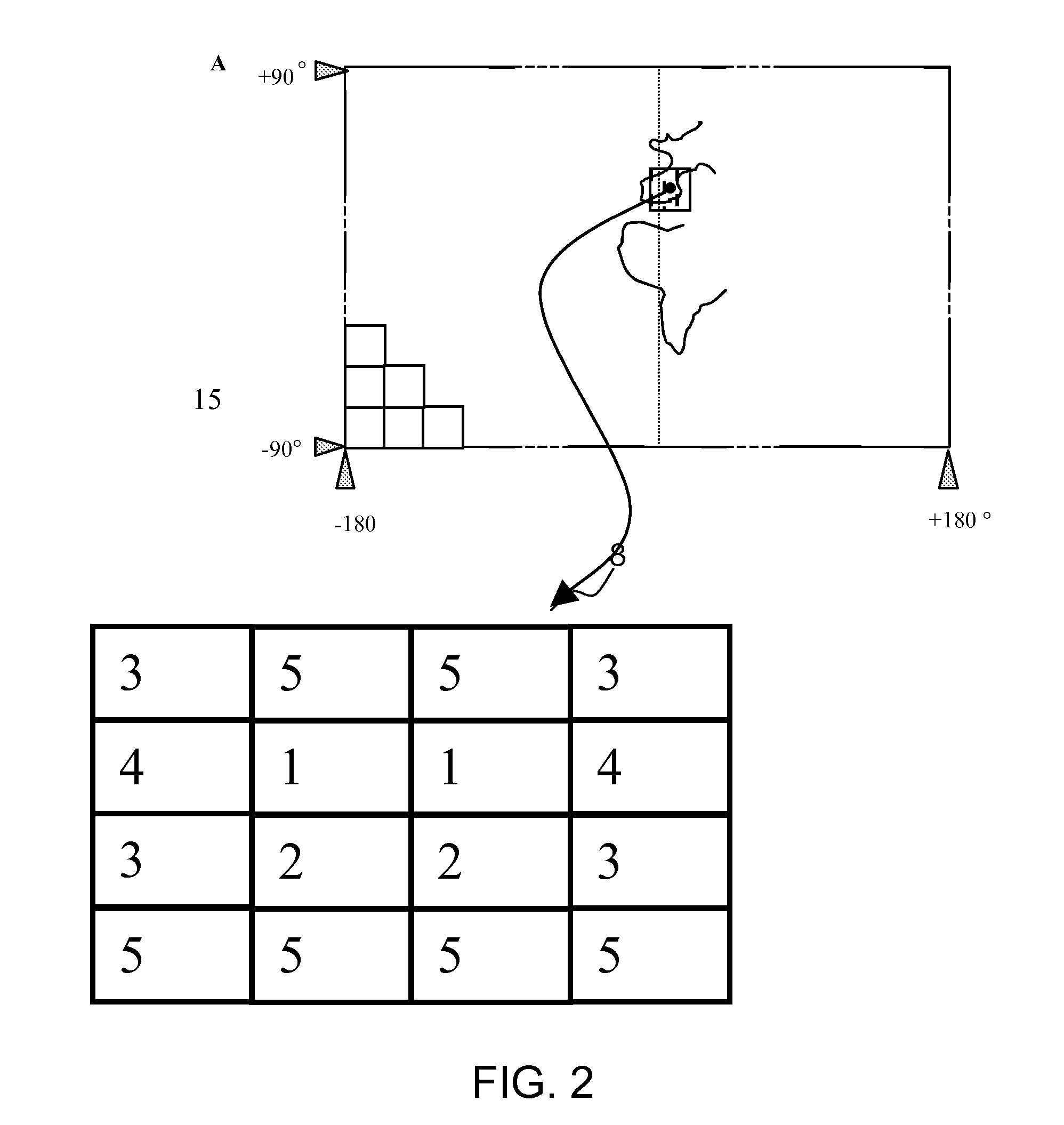
[0029]In a second embodiment, the cut-off frequencies and gain of the filter are associated with a density of obstacles. A plurality of density levels is configured in the monitoring system and filtering parameters are thus associated with each of the parameter setting levels. A first level of parameter setting, for the gain parameter K1 and the cut-off frequency parameters F1 and F1′, may be linked to a level 1 obstacle density. A second level of parameter setting, for the gain parameter K2 and the cut-off frequency parameters F2 and F2′, may be linked to a level 2 obstacle density. A third level of parameter setting, for the gain parameter K3 and the cut-off frequency parameters F3 and F3′, may be linked to a level 3 obstacle density. Other parameter setting levels may be configured in the monitoring system, the invention not being restricted to the aforementioned levels. According to the last two embodiments, the filtering parameters are associated with parameter setting levels p...
third embodiment
[0030]In a third embodiment, the cut-off frequencies and gain of the filter are determined automatically in real time as a function of current flight parameters such as the speed of the aircraft and the current obstacle density. In particular, the gain is determined as a function of the density of obstacles in the current flight area. The gain may also be weighted according to the type of mission performed by the aircraft. The obstacle density considered is the highest obstacle density within a radius of less than a given distance. By adjusting the filtering on the highest frequency of occurrence of obstacles, the influence of more scattered obstacles will accordingly be reduced. As for the cut-off frequencies of the filter, they are calculated automatically in real time as a function of the obstacle density and the aircraft speed. For determining the cut-off frequencies, it is assumed that the obstacles associated with a density N are evenly spread over the flight area and on avera...
PUM
 Abstract
Description
Claims
Application Information
 - R&D
- Intellectual Property
- Life Sciences
- Materials
- Tech Scout
- Unparalleled Data Quality
- Higher Quality Content
- 60% Fewer Hallucinations
Browse by: Latest US Patents, China's latest patents, Technical Efficacy Thesaurus, Application Domain, Technology Topic, Popular Technical Reports.
© 2025 PatSnap. All rights reserved.Legal|Privacy policy|Modern Slavery Act Transparency Statement|Sitemap|About US| Contact US: help@patsnap.com


