Probe connector

a technology of probe connectors and connectors, applied in the direction of coupling contact members, coupling device connections, instruments, etc., can solve the problems of difficult fixation of the contact point at the same position, and achieve the effect of increasing the occupation area, not easy to shift, and increasing the probe pitch

Inactive Publication Date: 2011-10-20
MOLEX INC
View PDF5 Cites 21 Cited by
  • Summary
  • Abstract
  • Description
  • Claims
  • Application Information

AI Technical Summary

Benefits of technology

[0006]An object of the present disclosure is to provide a probe connector in which the position of the coaxial probe is hardly displaced or deviated even when the coaxial plug is inserted thereto or pulled therefrom. Pursuant to this, there is provided a probe connector which connects a circuit board and a coaxial plug including an axial terminal and a surrounding terminal, the probe connector comprising a coaxial probe including a center terminal which is electrically connected to the axial terminal of the coaxial plug and to the circuit board, and an outer terminal which is coaxial with the center terminal and is electrically connected to the surrounding terminal and to the circuit board; wherein the outer terminal includes an outer conductor which is formed in a cylindrical shape surrounding the center terminal and is mated with the surrounding terminal, an anchor which is formed, as a projection, on part of an outer surface of the outer conductor so that a hole is formed on the part of the outer surface, and a conductive cover which covers the hole and which is electrically conducted to the outer conductor.

Problems solved by technology

Otherwise, it is difficult for the contact point to be fixed at the same position due to the cylindrical shape of the cylindrical contact.

Method used


Image

  • Probe connector
  • Probe connector
  • Probe connector

Examples


Embodiment Construction

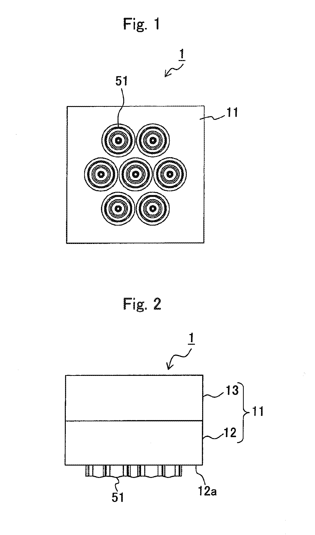
[0048]While the present disclosure may be susceptible to embodiment in different forms, there is shown in the figures, and will be described herein in detail, specific embodiments, with the understanding that the disclosure is to be considered an exemplification of the principles of the present disclosure, and is not intended to limit the present disclosure to that as illustrated. In the embodiments illustrated herein, representations of directions such as up, down, left, right, front, rear and the like, used for explaining the structure and movement of the various elements of the present disclosure, are not absolute, but relative. These representations are appropriate when the elements are in the position shown in the FIG. 2. If the description of the position of the elements changes, however, it is assumed that these representations are to be changed accordingly.

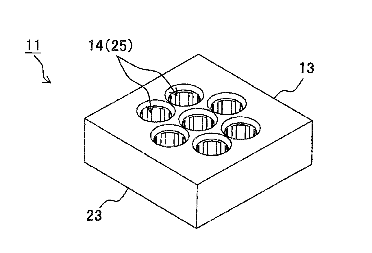
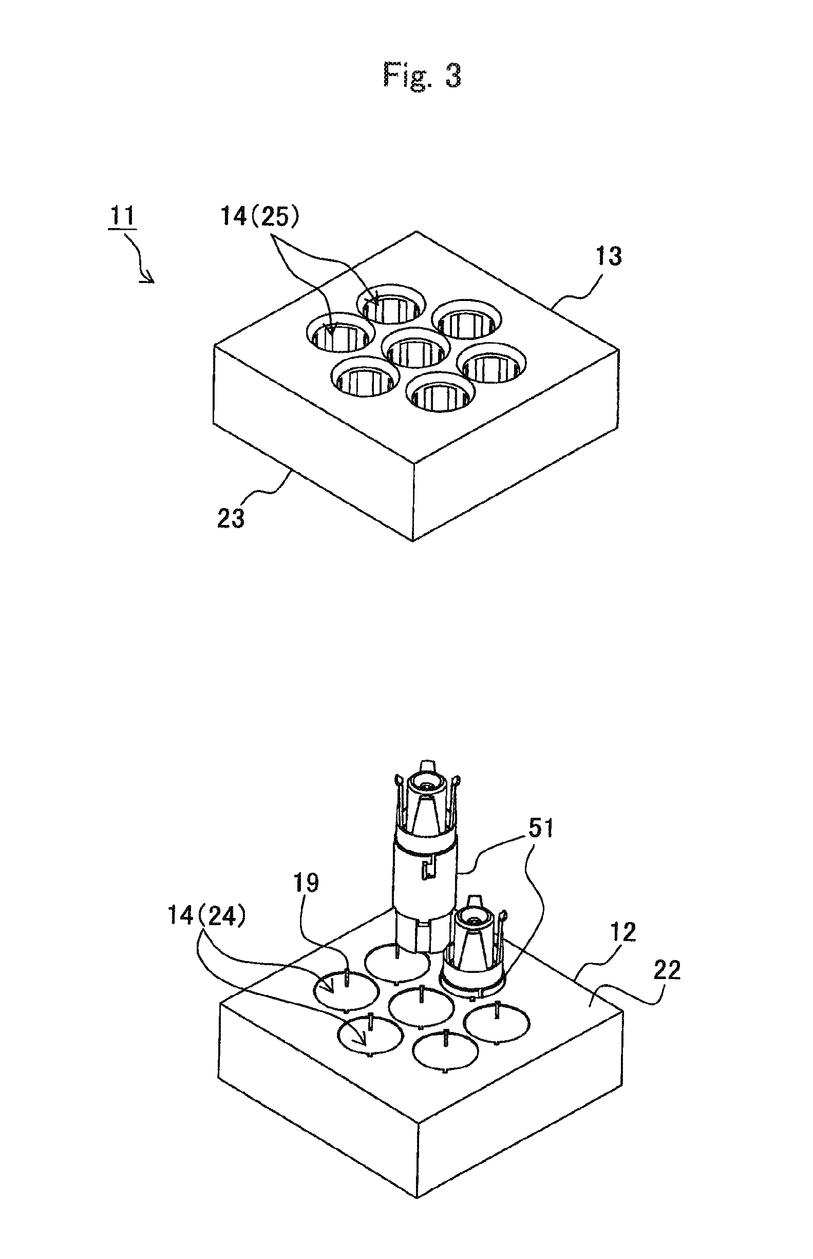
[0049]FIGS. 1-4 are views each showing a probe connector 1 of the embodiment. FIG. 1 is a front view of the probe connec...


PUM


Abstract

A probe connector (1) connects a circuit board (2) and a coaxial plug (3) including an axial terminal (162) and a surrounding terminal (163). A coaxial probe (51) of the probe connector includes a center terminal (52) connected to the circuit board and the axial terminal; and an outer terminal (61) coaxial with the center terminal and connected to the circuit board and the surrounding terminal. The outer terminal includes an cylindrical outer conductor (62) surrounding the center terminal and mated with the surrounding terminal; an anchor (63) formed, as a projection (69), on part of an outer surface of the outer conductor by machining process so that a hole is formed on the part of the outer surface; and a conductive cover (91) covering and closing the hole and electrically conducted to the outer conductor. Thus, the position of the coaxial probe is slightly shifted even when the coaxial plug is inserted thereto or pulled therefrom.

Description

BACKGROUND[0001]1. Field[0002]The Present Disclosure relates, generally, to a probe connector, and, more particularly, to a probe connector in which the position of the coaxial probe is slightly displaced or deviated when the coaxial plug is either inserted thereto or pulled therefrom.[0003]2. DESCRIPTION OF THE RELATED ART[0004]Japanese Utility Model Application No. 60-123666 purports to disclose a coaxial movable contact probe 851 used in an inspection apparatus, as shown in FIG. 16. The coaxial movable contact probe 851 includes a center conductor 852 and an outer conductor 861—having a plain cylindrical shape and surrounding the center conductor 852. As shown in FIG. 17, the probes 851 are held by a movable plate 802, which is movable relative to an inspection target circuit board 801 on which an inspection target Integrated Circuit (“IC”) is mounted. Further, coaxial connectors (“coaxial plugs”) 961 are connected to one end of the probes 851. Each coaxial plug 961 is connected,...

Claims


Application Information

Patent Timeline
Patent Type & Authority Applications(United States)
IPC IPC(8): G01R31/20H01R13/24H01R24/54
CPCG01R1/0416G01R1/06722G01R1/06772H01R12/714H01R13/2421H01R2201/20H01R13/17H01R12/71H01R13/24G01R1/067
Inventor UESAKA, RYOMIZUMURA, AKINORIMARONEY, JAMES
Owner MOLEX INC
Why Eureka
Try Eureka