Coaxial connector and measuring coaxial probe

a coaxial connector and coaxial probe technology, applied in the direction of coupling device connection, instruments, mechanical apparatus, etc., can solve the problems of increasing manufacturing costs, increasing components, and complicated structure, and achieves simple structure, easy attachment and removal, and withstand repeated use.

Active Publication Date: 2009-07-07
MURATA MFG CO LTD
View PDF26 Cites 14 Cited by
  • Summary
  • Abstract
  • Description
  • Claims
  • Application Information

AI Technical Summary

Benefits of technology

[0008]In order to overcome the problems described above, preferred embodiments of the present invention provide a coaxial connector and a measuring coaxial probe that have a simple structure, are easily attached to and detached from a receptacle, and withstand repetitive use.

Problems solved by technology

Therefore, the number of components is increased, the structure is complicated, and the manufacturing cost is increased.
Accordingly, the coaxial connector is easily deformed and deteriorated by repeating attachment and detachment to and from another connector.
Further, complicated operations are necessary for attachment and detachment to and from another connector.

Method used


Image

  • Coaxial connector and measuring coaxial probe
  • Coaxial connector and measuring coaxial probe
  • Coaxial connector and measuring coaxial probe

Examples


first preferred embodiment

See FIGS. 1 to 7

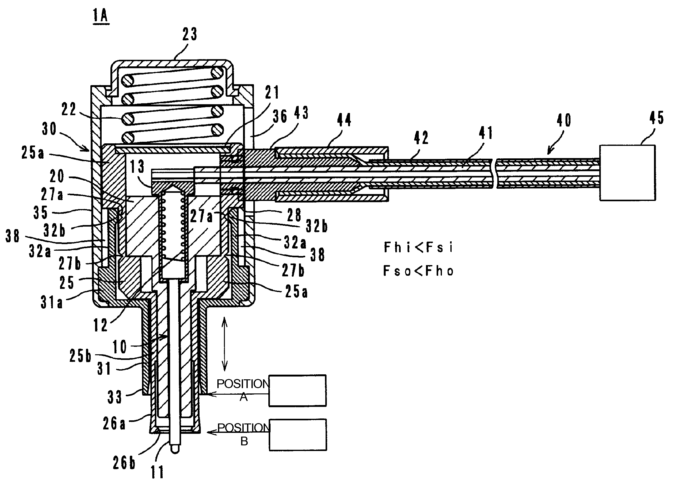
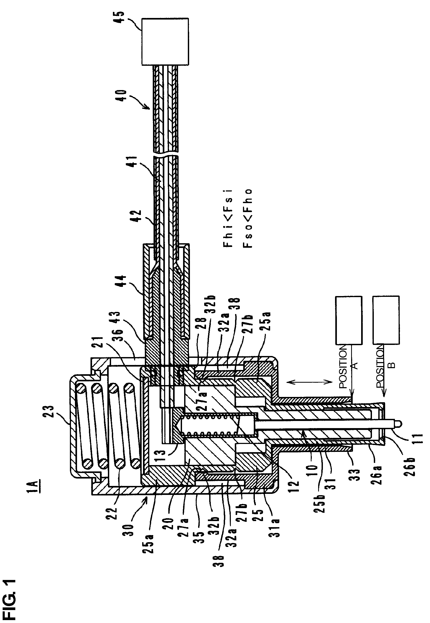
[0030]A measuring coaxial probe 1A according to a first preferred embodiment of the present invention includes a central conductor probe 10, a bushing 20, a housing 25, a sleeve 30, a disc 21, a coil spring 22, and a cap 23, as shown in FIG. 1. In a receptacle 2, a case 3 having a center hole 4 is provided with a ground terminal (outer conductor) 5, a first inner terminal 6, and a second inner terminal 7, as shown in FIGS. 7A-7C. The second inner terminal 7 is in elastic contact with the first inner terminal 6 from below. The second inner terminal 7 is in contact with the first inner terminal 6 because of its spring force. When being pressed by a plunger 11 of the measuring coaxial probe 1A, as will be described below, the second inner terminal 7 is bent downward and is separated from the first inner terminal 6.

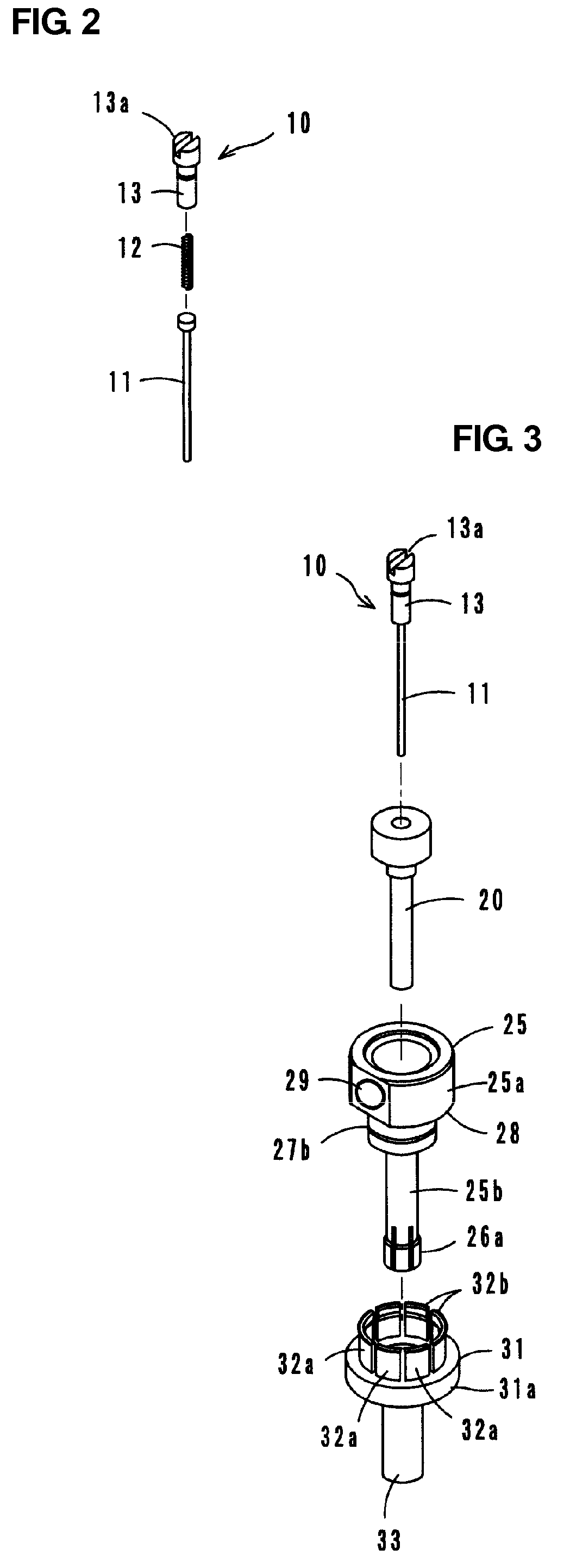
[0031]The central conductor probe 10 includes a plunger 11, a coil spring 12, and a barrel 13 each of which is formed of a conductive material. An upper porti...

second preferred embodiment

See FIGS. 8A and 8B

[0052]FIGS. 8A and 8B show a measuring coaxial probe 1B according to a second preferred embodiment of the present invention. In the measuring coaxial probe 1B, the cap 23 used in the above-described first preferred embodiment is not provided, a ceiling portion 37 is provided in a second sleeve 35, and a coil spring 22 is interposed between the ceiling portion 37 and a disc 21 disposed at an upper end of a housing 25. Other structures, operations, and operational advantages are similar to those adopted in the first preferred embodiment. In FIGS. 8A and 8B, the same components and portions as those in FIG. 1 are denoted by common reference numerals, and redundant descriptions thereof are omitted.

third preferred embodiment

See FIG. 9

[0053]The coil spring 22 adopted in the first and second preferred embodiments is not indispensable. FIG. 9 shows a measuring coaxial probe 1C according to a third preferred embodiment in which the coil spring 22 is not provided. In this case, an upper end of a second sleeve 35 is simply covered with a cap 24. Other structures, operations, and operational advantages are similar to those adopted in the first preferred embodiment. In FIG. 9, the same components and portions as those in FIG. 1 are denoted by common reference numerals, and redundant descriptions thereof are omitted.

Characteristic Measurement, See FIG. 10

[0054]A description will now be given of measurement of the electrical characteristics of a mobile telephone with the measuring coaxial probe. FIG. 10 shows a high-frequency circuit of a mobile telephone 120. The high-frequency circuit includes an antenna element 122, a duplexer 123, a transmission isolator 131, a transmission amplifier 132, a transmission inte...


PUM


Abstract

A coaxial connector is connected to a leading end of a coaxial cable and is detachably connected to a receptacle. The coaxial connector includes a cylindrical housing including a spring portion having a projection to be fitted in a groove provided on the outer periphery of an outer conductor of the receptacle, a central conductor probe stored in the housing so as to be in contact with an inner terminal of the receptacle, and cylindrical sleeves held on the outer periphery of the housing so as to be movable in the axial direction. The sleeve has lock pieces provided in an upper portion and an annular portion in a lower portion. The lock pieces are in elastic contact with a first engaging portion and a second engaging portion provided on the outer periphery of the housing. The annular portion restricts expansion of the spring portion of the housing. The annular portion of the sleeve does not restrict the spring portion when detached (position A), and restricts expansion of the spring portion when attached (position B).

Description

BACKGROUND OF THE INVENTION[0001]1. Field of the Invention[0002]The present invention relates to a coaxial connector, and more particularly, to a coaxial connector and a measuring coaxial probe connected to a leading end of a coaxial cable and detachably connected to a receptacle.[0003]2. Description of the Related Art[0004]A known coaxial connector is described in Japanese Unexamined Patent Application Publication No. H10-32042.[0005]As shown in FIG. 11, the coaxial connector includes a sleeve (a movable member 116 and a coupling nut 117) that holds an outer conductor member 115 from the outside and that is movable in the axial direction.[0006]Unfortunately, the sleeve provided outside the outer conductor member 115 in this coaxial connector is defined by the movable member 116 and the coupling nut 117 that are independently movable, and two coil springs 120 and 121 are provided. The movable member 116 includes a spring portion 116a, and a projection 116b is provided at the leading...

Claims


Application Information

Patent Timeline
Patent Type & Authority Patents(United States)
IPC IPC(8): H01R9/05H01R13/646
CPCG01R1/06772H01R24/40H01R13/4538G01R1/06788H01R2201/20H01R2103/00
Inventor WAKAMATSU, HIROKIMARUYAMA, YUICHIOSAKI, YOSHIHIRO
Owner MURATA MFG CO LTD
Why Eureka
Try Eureka