Liquid crystal display apparatus

a display device and liquid crystal technology, applied in the field of liquid crystal display devices, can solve the problems of increasing cost and reducing yield, and achieve the effect of minimizing the decrease in display quality and improving viewing angle characteristics

Inactive Publication Date: 2011-10-20
SHARP KK
View PDF1 Cites 27 Cited by
  • Summary
  • Abstract
  • Description
  • Claims
  • Application Information

AI Technical Summary

Benefits of technology

[0031]The present invention provides a liquid crystal display device that can improve the viewing angle characteristic and minimize the decrease in display quality.

Problems solved by technology

Nevertheless, to make those regions of each subpixel have mutually different luminances, fine electrodes should be provided for those regions of each subpixel, thus increasing the cost and sometimes resulting in a decreased yield.

Method used


Image

  • Liquid crystal display apparatus
  • Liquid crystal display apparatus
  • Liquid crystal display apparatus

Examples


embodiment 1

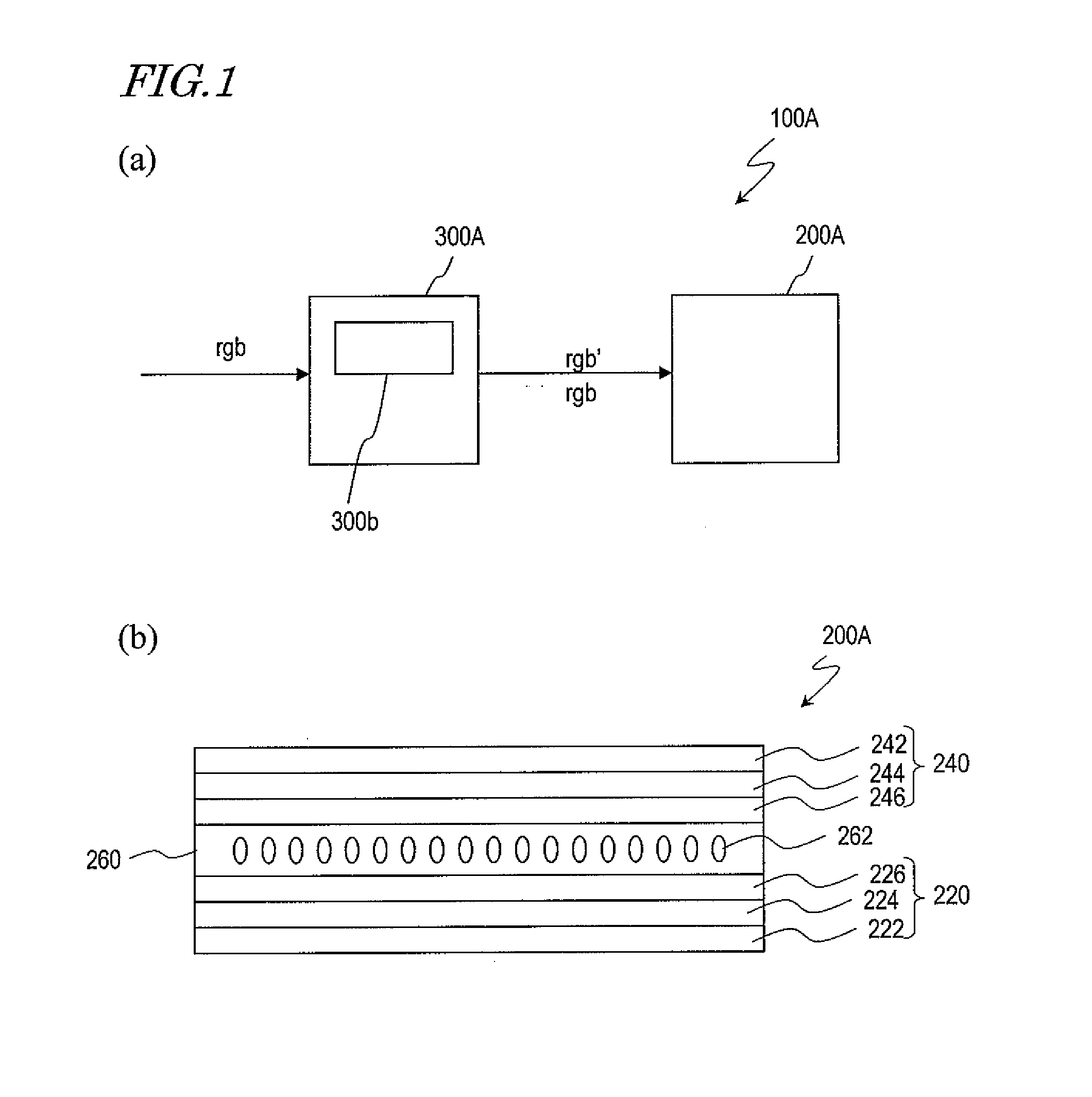
[0084]A first specific preferred embodiment of a liquid crystal display device according to the present invention will now be described. FIG. 1(a) is a schematic representation illustrating a liquid crystal display device 100A as a first preferred embodiment of the present invention. The liquid crystal display device 100A includes an LCD panel 200A and a correcting section 300A. The LCD panel 200A has a number of pixels that are arranged in columns and rows to form a matrix pattern. In the LCD panel 200A of this preferred embodiment, each of those pixels includes red, green and blue subpixels. In the following description, the liquid crystal display device will sometimes be simply referred to herein as just a “display device”.

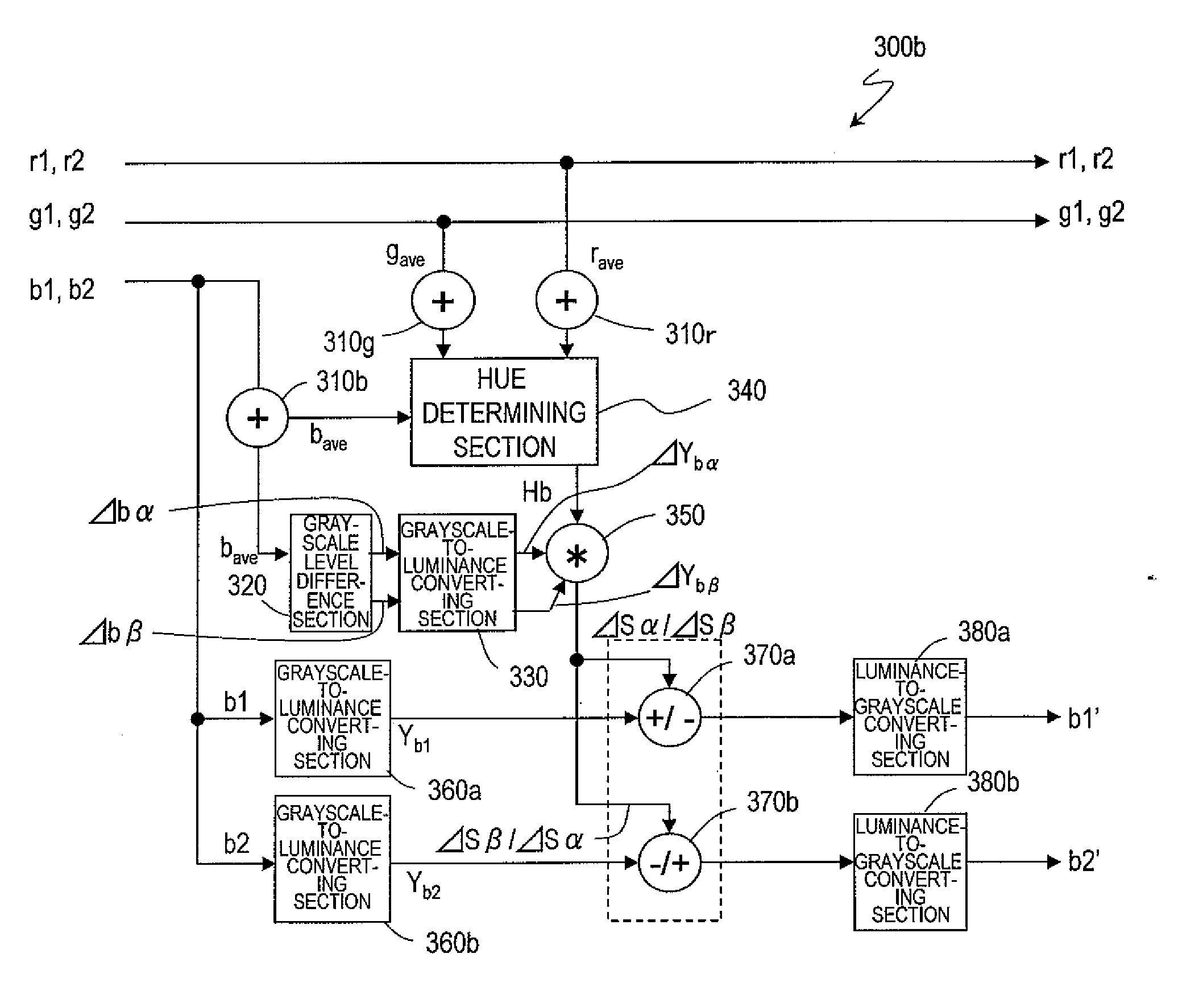
[0085]The correcting section 300A makes correction on at least one of the grayscale levels (or its associated luminance levels) of red, green and blue subpixels as indicated by the input signal when one condition is satisfied but does not make the correction wh...

embodiment 2

[0214]In the preferred embodiment described above, each subpixel is supposed to have a single luminance. However, the present invention is in no way limited to that specific preferred embodiment. Optionally, a multi-pixel structure may be adopted and each subpixel may have multiple regions with mutually different luminances.

[0215]Hereinafter, a second specific preferred embodiment of a liquid crystal display device according to the present invention will be described with reference to FIG. 27. The liquid crystal display device 100B of this preferred embodiment includes an LCD panel 200B and a correcting section 300B, which also includes a blue correcting section 300b. This liquid crystal display device 100B has the same configuration as its counterpart of the first preferred embodiment described above except that each subpixel in the LCD panel 200B has multiple regions that may have mutually different luminances and that the effective potential of a divided electrode that defines su...

embodiment 3

[0231]In the preferred embodiments of the present invention described above, the luminance is supposed to be controlled using two subpixels belonging to two adjacent pixels as a unit. However, the present invention is in no way limited to those specific preferred embodiments. Optionally, the luminance may also be controlled using multiple different regions of a single subpixel as a unit.

[0232]Hereinafter, a third specific preferred embodiment of a liquid crystal display device according to the present invention will be described with reference to FIG. 30. The liquid crystal display device 100C of this preferred embodiment includes an LCD panel 200C and a correcting section 300C, which also includes a blue correcting section 300b. This liquid crystal display device 100C has the same configuration as its counterpart of the first preferred embodiment described above except that each subpixel has multiple regions, of which the luminances can be different from each other, in the LCD pane...


PUM


Abstract

A liquid crystal device (100A) according to the present invention has first and second pixels (P1 and P2). Each of the first and second pixels (P1 and P2) includes first, second and third subpixels (R, G, and B). When the input signal indicates that each pixel should represent the first color, the luminances of the respective third subpixels (B1 and B2) of the first and second pixels (P1 and P2) are different from each other. But when the input signal indicates that each pixel should represent the second color, the average luminance of the respective third subpixels (B1 and B2) is substantially the same as when the first color is specified, and the luminances of the respective third subpixels (B1 and B2) are substantially equal to each other.

Description

TECHNICAL FIELD[0001]The present invention relates to a liquid crystal display device.BACKGROUND ART[0002]Liquid crystal displays (LCDs) have been used in not only TV sets with a big screen but also small display devices such as the monitor screen of a cellphone. In an LCD, one pixel consists of three subpixels representing red (R), green (G) and blue (B) that are the three primary colors of light, and the difference in color between those red, green and blue subpixels is typically produced by color filters.[0003]TN (twisted nematic) mode LCDs, which would often be used in the past, achieved relatively narrow viewing angles, but LCDs of various other modes with wider viewing angles have recently been developed one after another. Examples of those wider viewing angle modes include IPS (in-plane switching) mode and VA (vertical alignment) mode. Among those wide viewing angle modes, the VA mode is adopted in a lot of LCDs because the VA mode would achieve a sufficiently high contrast r...

Claims


Application Information

Patent Timeline
Patent Type & Authority Applications(United States)
IPC IPC(8): G09G3/36G09G5/02
CPCG02F2201/52G09G3/3607G09G3/3648G09G2300/0443G09G2300/0452G09G2340/06G09G2320/0271G09G2320/0285G09G2320/068G09G2340/0457G09G2320/0242G02F1/13306G09G3/2074G02F1/133G09G3/36
Inventor MORI, TOMOHIKOTOMIZAWA, KAZUNARIYOSHIDA, YUICHI
Owner SHARP KK
Why Eureka
Try Eureka