
Spiral staircase

a spiral staircase and spiral technology, applied in the direction of stairs, staircases, building constructions, etc., can solve the problems of difficult operation, difficult to reach the end of the steps, and the surface available for supporting the sole of the foot, so as to facilitate the ascending and descending of the spiral staircase. , the effect of increasing the number of steps

Inactive Publication Date: 2011-10-27
ALBINI & FONTANOT
View PDF7 Cites 1 Cited by
  • Summary
  • Abstract
  • Description
  • Claims
  • Application Information

AI Technical Summary

Benefits of technology

The invention is a staircase design that makes it easier to ascend and descend, providing more stability and balance for users. The steps have a shape that increases the surface area for support, and the landing can have more steps, reducing the riser and creating a similar ratio to straight ramps. The design also allows for flexibility to cover any height, adapting to different plan shapes and directions of rotation. The invention can be made from various materials and colors.

Problems solved by technology

The technical problem addressed in this patent relates to making improvements in spiral staircases where there may be limited space availability, particularly for individuals who have a normal built-in size but find the narrowness of the steps challenging when ascending or descending. Additionally, the spacing of the steps often results in insufficient stable surfaces for the feet, especially when walking downwards. Current solution designs also fail to provide optimal ratios of riser to tread for efficient use of space and favor one foot over another.

Method used


Image

  • Spiral staircase
  • Spiral staircase
  • Spiral staircase

Examples


Embodiment Construction

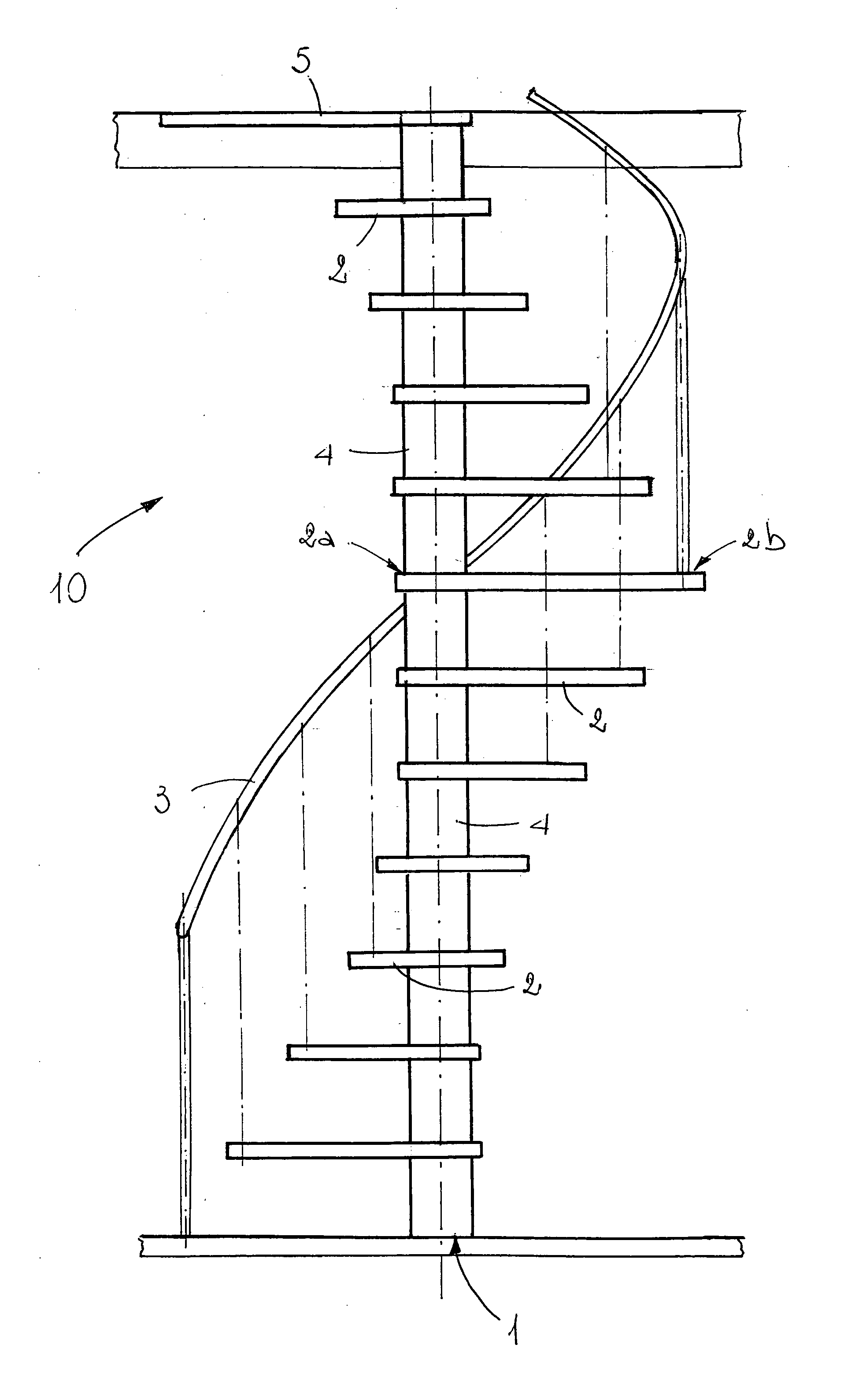
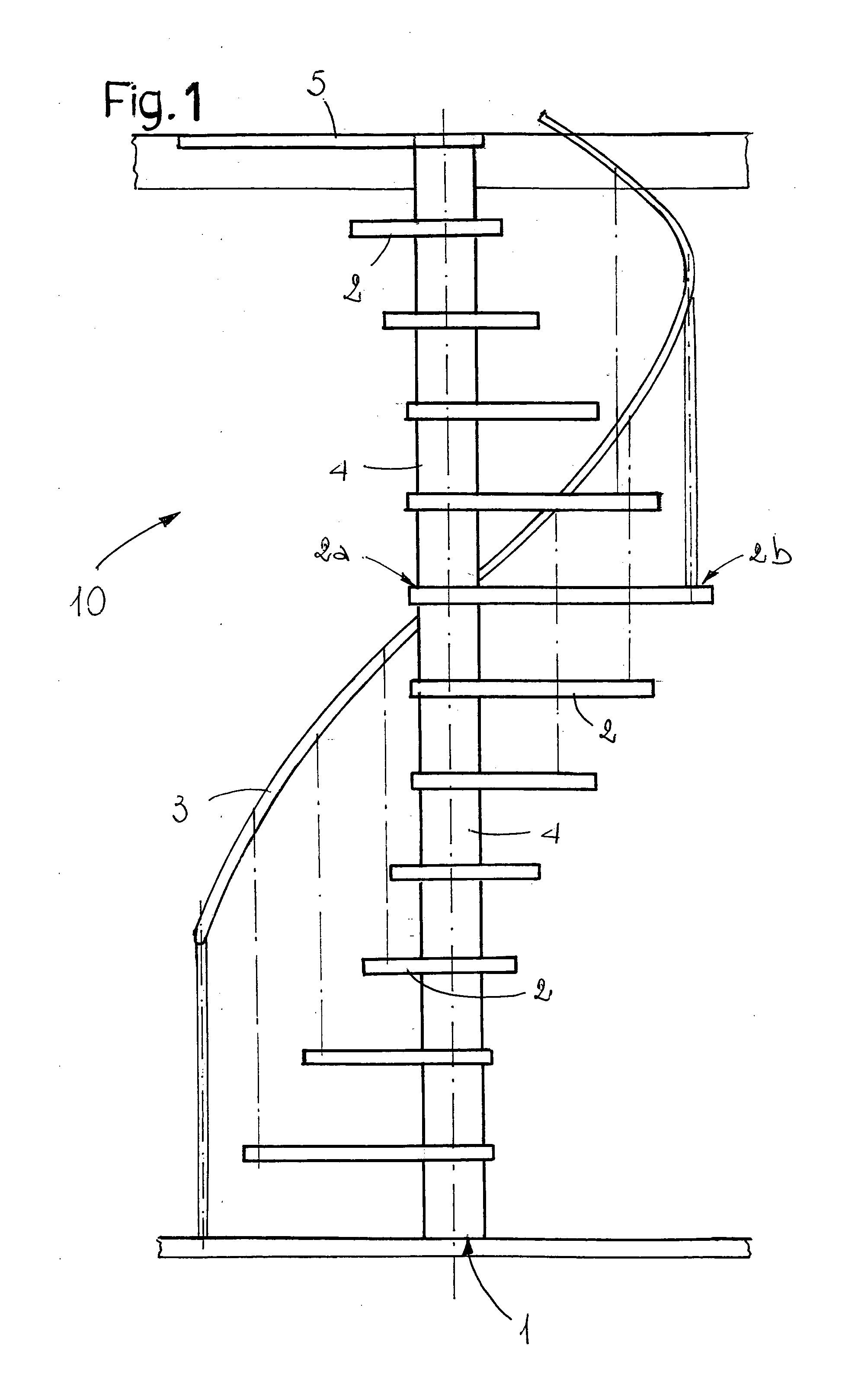
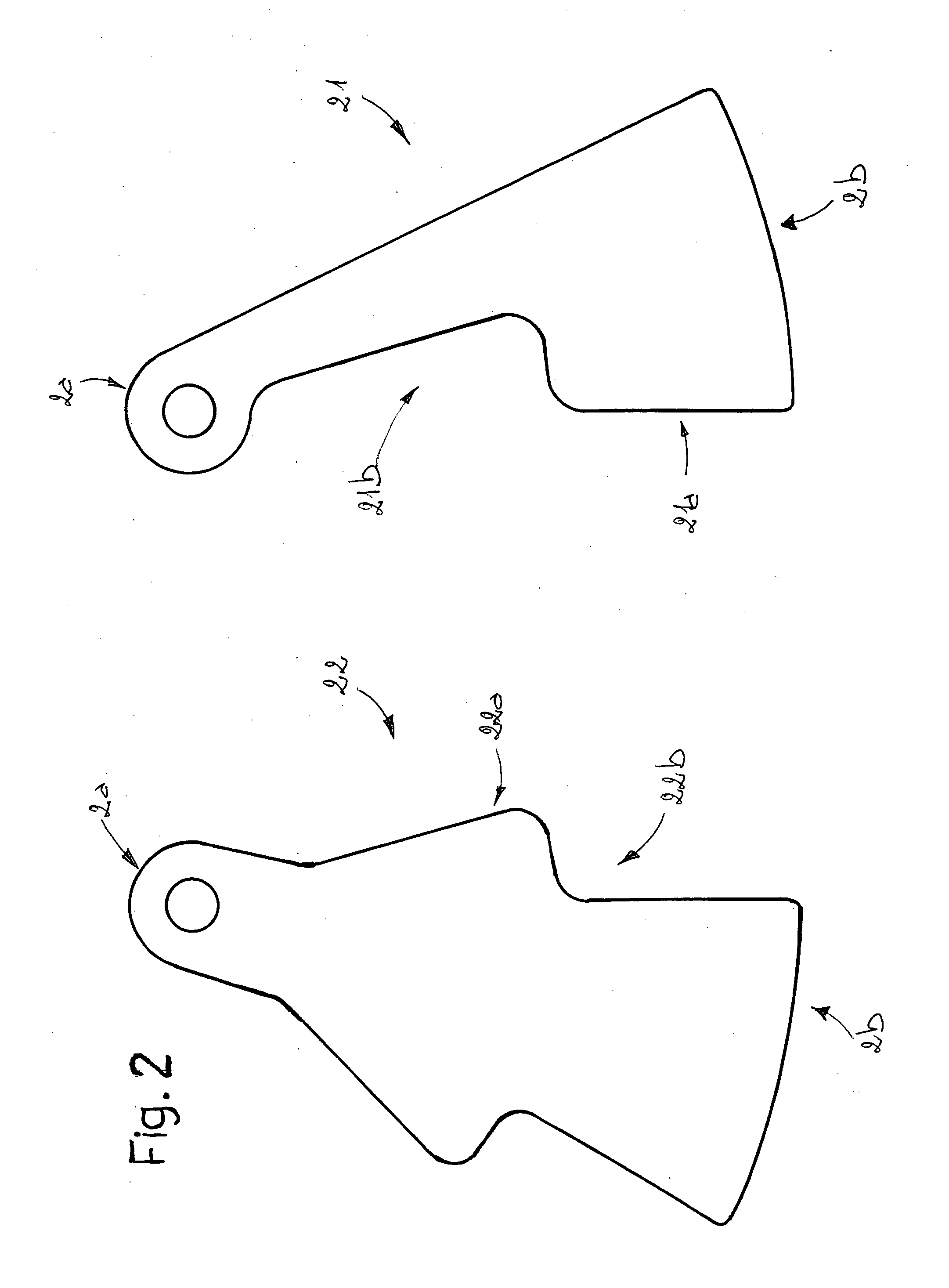
[0018]In accordance with the accompanying drawings, the invention relates to a spiral staircase. It comprises a central supporting element (1) and a plurality of steps (2), which are connected to the supporting element (1) at a first end (2a). In particular, as shown in FIGS. 2 and 4, it comprises two types of steps (21, 22), where a first type of step (21) is substantially “L”-shaped and a second type of step (22) is substantially arrow-shaped. They are positioned along the staircase (10) in an alternating fashion, as shown in the detail in FIG. 3.

[0019]The first type of step (21) comprises at least one projection (21a) and one recess (21b) which complement at least one projection (22a) and one recess (22b) of the second type of step (22). The projections (21a, 22a) and recesses (21b, 22b) contribute to forming on the steps (21, 22) treadable portions (21c, 22c) which are separate from portions (21d, 22d) that are not strictly necessary for achieving the advantages which the invent...


PUM


Abstract

A spiral staircase comprises a central supporting element and a plurality of steps which are connected to the supporting element at a first end, there being two types of steps positioned in an alternating fashion, of which a first type of step is substantially “L”-shaped and a second type of step is substantially arrow-shaped.

Description


Claims


Application Information

Patent Timeline
Owner ALBINI & FONTANOT
Features
  • Generate Ideas
  • Intellectual Property
  • Life Sciences
  • Materials
  • Tech Scout
  • Unparalleled Data Quality
  • Higher Quality Content
  • 60% Fewer Hallucinations
Learn More