
Control device, communication terminal, control method, and communication method

a control device and communication terminal technology, applied in the field of control devices, communication terminals, control methods, communication methods, etc., can solve problems such as system or network interference, and achieve the effect of avoiding interferen

Active Publication Date: 2011-10-27
SOVEREIGN PEAK VENTURES LLC
View PDF16 Cites 18 Cited by
  • Summary
  • Abstract
  • Description
  • Claims
  • Application Information

AI Technical Summary

Benefits of technology

[0063]As described above, according to the present invention, when the control device determines that influence of interference from another network system is large in communication with the communication terminal, the control device selects a channel from a plurality of channels so as to avoid the interference from the another network system, and causes the communication terminal within the network to change the use channel in a short time. Thereby, communication between the control device and the communication terminal can be unfailingly realized by using the changed channel.

Problems solved by technology

This causes a problem of interference between systems or between networks.
Moreover, in a case where a system having large transmission power is used in an adjacent frequency band, for example, in a case where a mobile phone or the like is used, a wireless terminal which uses a simple, small-size radio frequency component such as an active RF tag cannot obtain channel selectivity and thus may suffer from interference.

Method used


Image

  • Control device, communication terminal, control method, and communication method
  • Control device, communication terminal, control method, and communication method
  • Control device, communication terminal, control method, and communication method

Examples


first embodiment

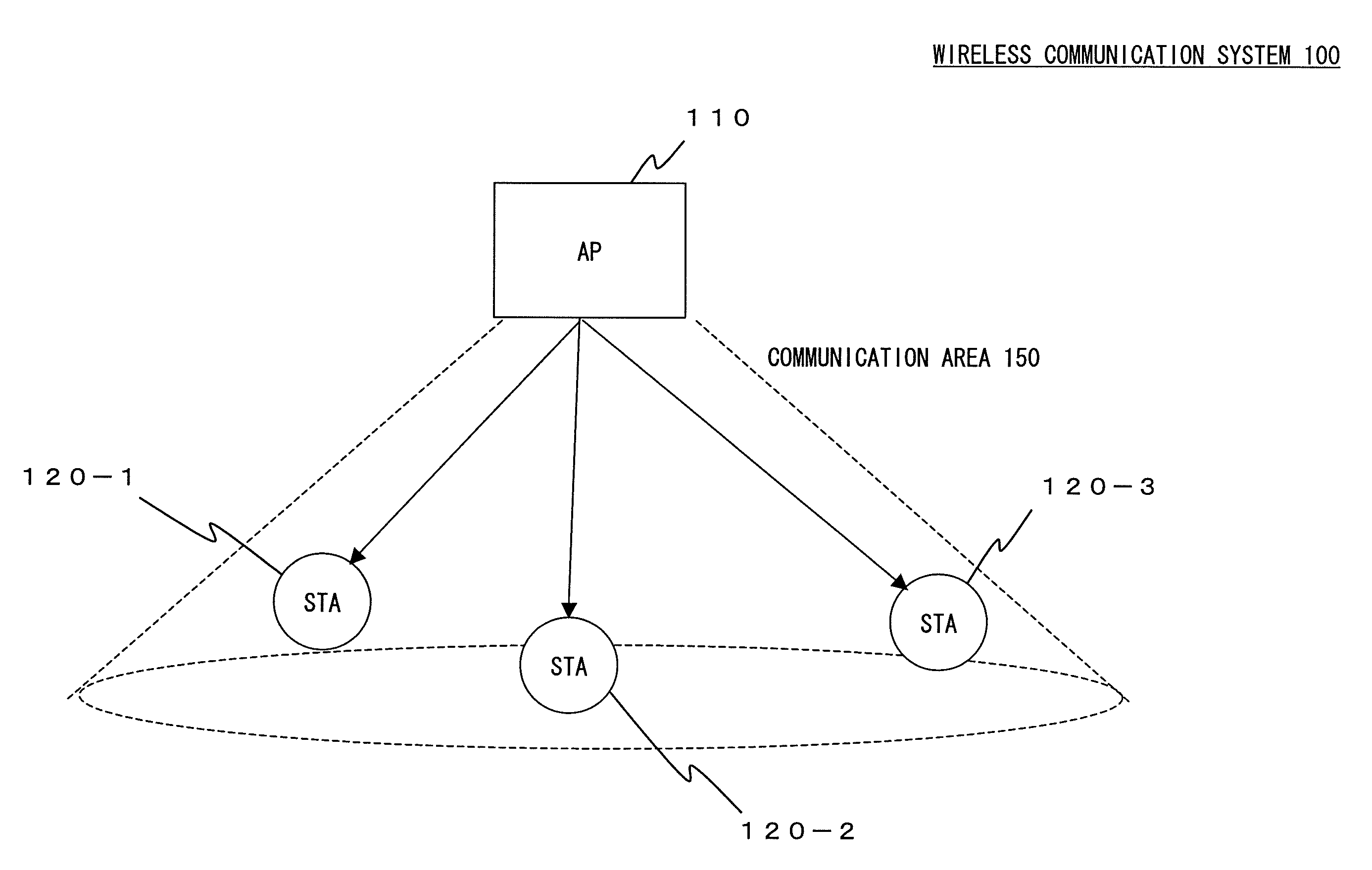
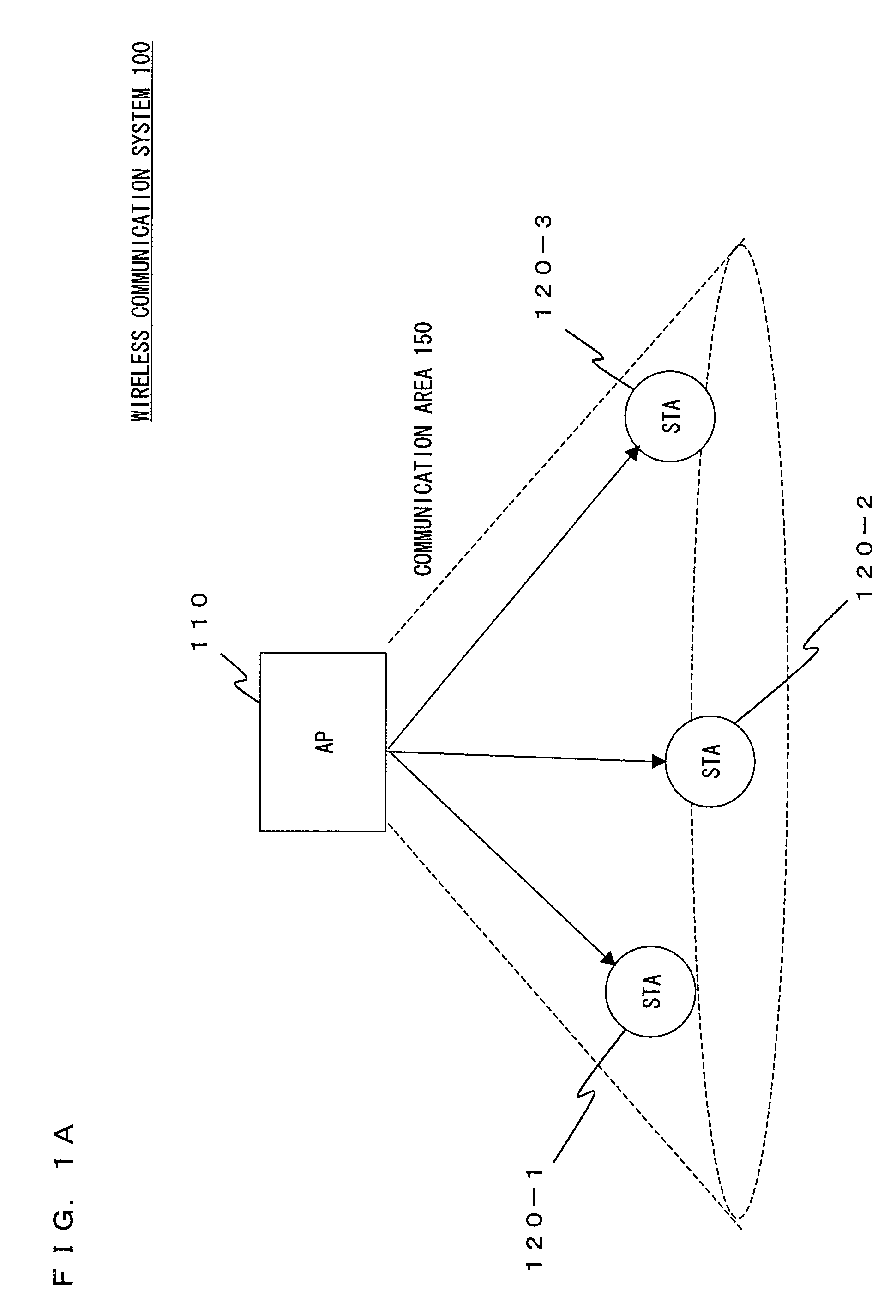
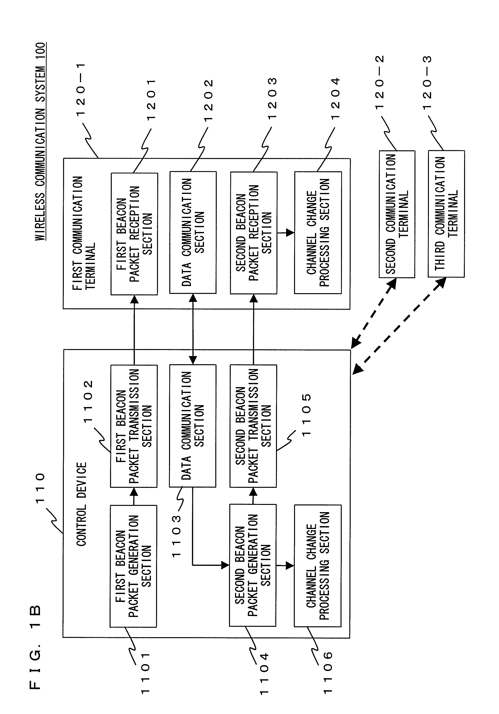
[0085]FIG. 1A shows a wireless communication system 100 according to a first embodiment of the present invention. In FIG. 1A, the wireless communication system 100 includes a control device (AP: Access Point) 110 and first to third communication terminals (STA: Station) 120-1 to 120-3. The first to third communication terminals 120-1 to 120-3 exist within a communication area 150 of the control device 110. The control device 110 periodically broadcasts a beacon packet to the first to third communication terminals 120-1 to 120-3 which are all the communication terminals existing within the communication area 150. The beacon packet includes control information. Each of the first to third communication terminals 120-1 to 120-3 receives the beacon packet from the control device 110, and communicates with the control device 110 based on the control information included in the beacon packet. In this manner, a configuration of the wireless communication system 100 is basically the same as ...

second embodiment

[0162]In the first embodiment of the present invention, the case where each of the communication terminals 120-1 to 120-3 successfully receives the first beacon packet and the second beacon packet from the control device 110, has been described. In the present embodiment, a case where each of the communication terminals 120-1 to 120-3 fails to receive the first beacon packet from the control device 110, will be described.

[0163]FIG. 11 shows a control flow of each of communication terminals 120-1 to 120-3 according to the second embodiment of the present invention. Here, a control flow of the first communication terminal 120-1 will be described. In FIG. 11, the process in steps S201 to S206 is the same as that in the first communication terminal 120-1 according to the first embodiment of the present invention shown in FIG. 10, and therefore a description thereof is omitted.

[0164]In step S210, the first communication terminal 120-1 determines whether or not the first beacon packet is ...

third embodiment

[0172]In the second embodiment of the present invention, the case where each of the communication terminals 120-1 to 120-3 fails to receive the first beacon packet from the control device 110, has been described. In the present embodiment, a case where each of the communication terminals 120-1 to 120-3 fails to receive the second beacon packet from the control device 110, will be described.

[0173]FIG. 12 shows a communication sequence between the control device 110 and each of the communication terminals 120-1 to 120-3 in the wireless communication system 100, in a case where a reception of the second beacon packet fails. The communication sequence shown in FIG. 12 is basically the same as the communication sequence according to the first embodiment of the present invention shown in FIG. 8, and therefore a detailed description is omitted. In the present embodiment, points where the communication sequence according to the present embodiment is different from the communication sequence...


PUM


Abstract

In a wireless communication system according to the present invention: a control device and a communication terminal communicate in an active period. The control device: generates a first beacon packet including one or more candidate channels; transmits the first beacon packet at the beginning of the active period; determines whether or not a use channel is to be changed based on a communication state, and generates a second beacon packet including information of a determination result; transmits the second beacon packet at the end of the active period; and, when it is determined that the use channel is to be changed, changes the use channel after the active period ends and before a next active period starts. The communication terminal: receives the first and second beacon packets; and, based on the second beacon packet, changes the use channel after the active period ends and before a next active period starts.

Description

TECHNICAL FIELD[0001]The present invention relates to a control device, a communication terminal, a control method, and a communication method, which are used for a wireless communication system, and more particularly relates to a control device, a communication terminal, a control method, and a communication method, which avoid interference caused by a plurality of channels being used in a sensor network or a wireless communication network using an active RF (Radio Frequency) tag.BACKGROUND ART[0002]In recent years, there has been an increasing interest in a network that uses a small-size, low-power-consumption wireless terminal, such as a WPAN (Wireless Personal Area Network) and a sensor network. Also, as a system similar to the network, an active RF tag system that transmits a wireless signal by itself, can be mentioned.[0003]FIG. 13 shows a conventional wireless communication system 10. In FIG. 13, the wireless communication system 10 includes a control device (AP: Access Point...

Claims


Application Information

Patent Timeline
Patent Type & Authority Applications(United States)
IPC IPC(8): H04W72/04H04W72/54
CPCH04W72/042H04W84/10H04W72/082H04W72/541H04W72/23
Inventor SHIRAKATA, NAGANORINAKAE, HIRONORIIMAMURA, KOJI
Owner SOVEREIGN PEAK VENTURES LLC
Learn More