Screw compressor with asymmetric ports

Active Publication Date: 2011-10-27
CARRIER CORP
View PDF11 Cites 6 Cited by
  • Summary
  • Abstract
  • Description
  • Claims
  • Application Information

AI Technical Summary

Problems solved by technology

This increase in fluid flow velocity, (and associated pressure pulsations) causes noise that may be disturbing to individuals located near the system, and may cause pressure pulsations and vibrations in various other system components that may damage the system components.
The pressure pulsations may also decrease the efficiency of the compressor.
It is often difficult to adapt the internal pressure to be equal to the discharge channel pressure.
Similarly, a change in suction flow rate may also cause suction pressure pulsations and fluid flow surges in the suction channel upstream of the suction ports.
These pulsations may result in undesirable noise and vibration, and may also detrimentally affect system operating efficiency.
Thus, in a typical multi-rotor compressor the simultaneous opening and closing of multiple compression pockets has the undesirable effect of increasing the flow velocity of working fluid to and from the channels, as the internal pressure of several compression pockets open simultaneously to the channel and must be equalized with the pressure in the channel.

Method used


Image

  • Screw compressor with asymmetric ports
  • Screw compressor with asymmetric ports
  • Screw compressor with asymmetric ports

Examples


Embodiment Construction

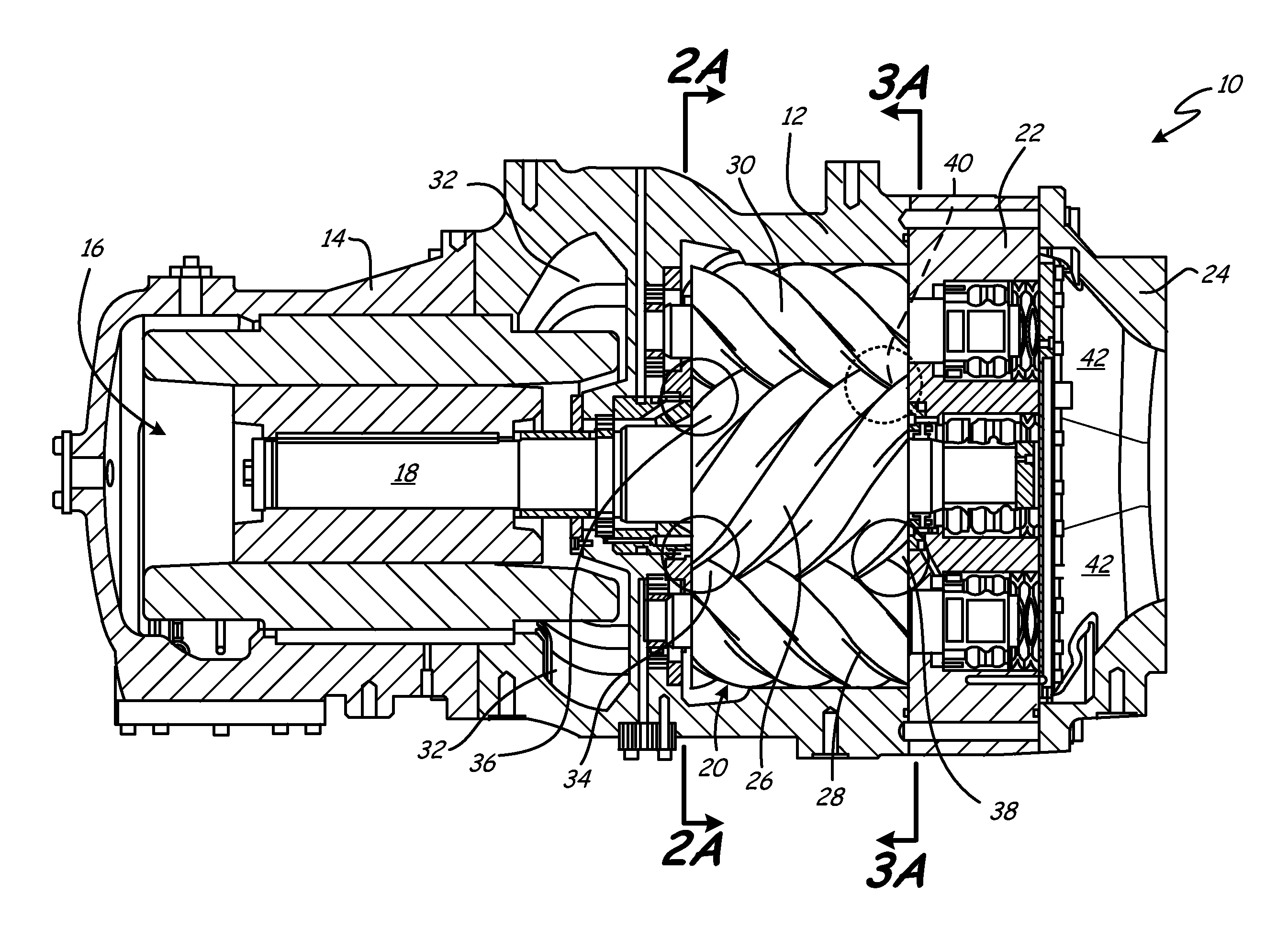
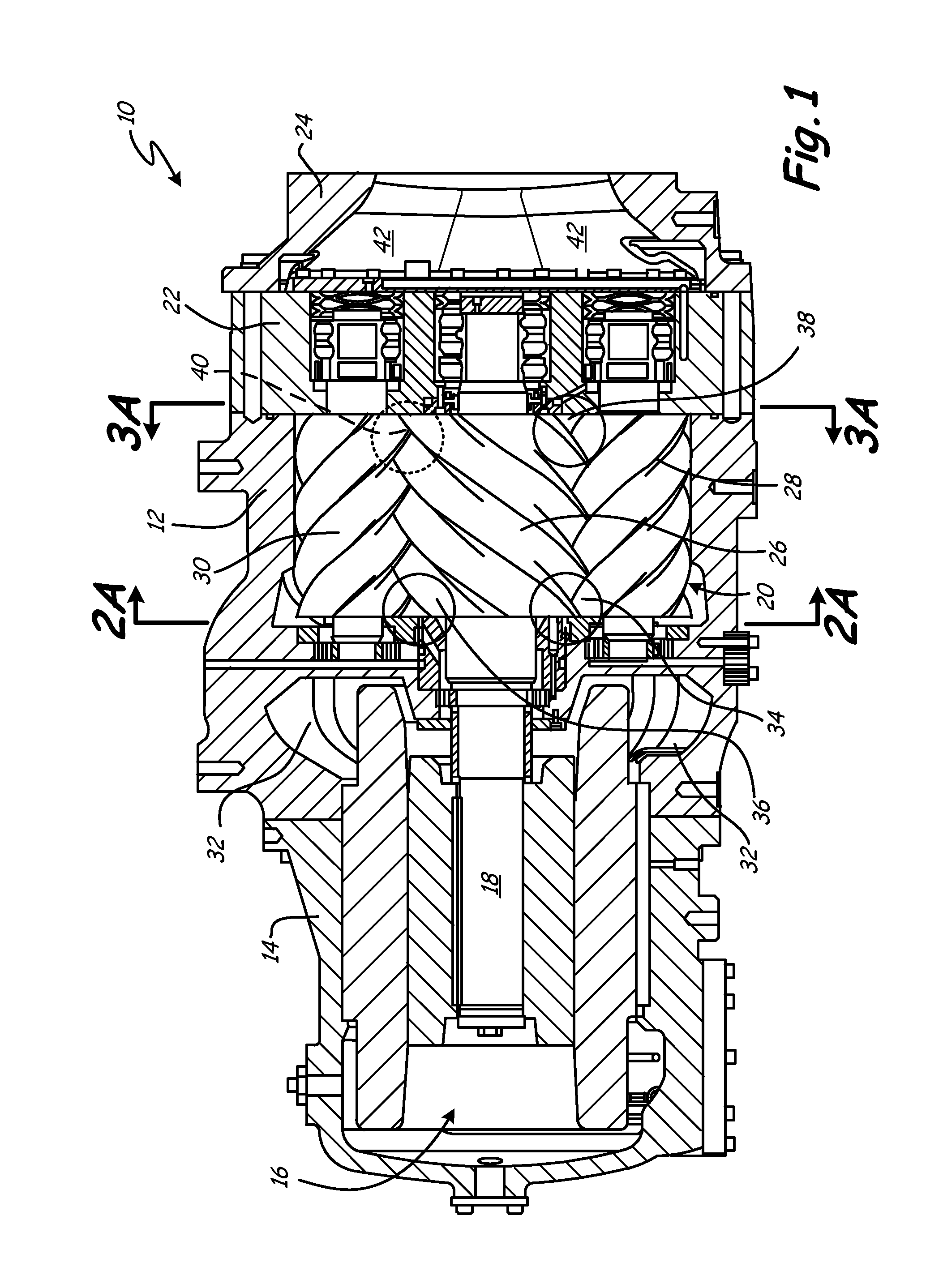
FIG. 1 is a top sectional view of a compressor 10 in accordance with the present invention including a rotor housing section 12, a motor housing section 14, a motor 16, a drive shaft 18, rotors 20, a discharge housing section 22, and a discharge housing cover 24. As known in the art, instead of an electric motor driven design, the rotors 20 can be driven by other means, as for example by being coupled to an engine. The rotors 20 include a sun rotor 26, a first planet rotor 28, and a second planet rotor 30. The motor housing section 14 defines a suction channel 32. The rotor housing section 12 defines a first suction port 34 and a second suction port 36. The discharge housing section 22 defines a first discharge port 38 and a second discharge port 40. The second discharge port 40 is disposed on the opposite radial side of the rotors 20 (thus would be visible to the viewer from a bottom sectional view of the compressor 10), and therefore, is shown with a dashed line. The discharge hou...


PUM


Abstract

A multi-rotor screw compressor includes a housing, a sun rotor, and first and second planet rotors. The first planet rotor intermeshes with the sun rotor to define a first compression pair. The second planet rotor intermeshes with the sun rotor to define a second compression pair. The first and second compression pairs are rotatably mounted in the housing. The housing includes a first port, a portion of which is in communication with the first compression pair, and a second port, a portion of which is in communication with the second compression pair. The portions of the first and second ports which communicate with the first and second compression pairs have a different geometry for offsetting pulsations in a working fluid flowing through the ports.

Description

BACKGROUNDThe present invention relates to helical screw compressors. More particularly, the present invention relates to a multi-rotor screw compressor having three or more rotors.Multi-rotor screw type compressors are typically used to compress various working fluids for air conditioning and refrigeration applications. Multi-rotor compressors generally include a housing to enclose and protect the interior components of the compressor (such as the rotors). In a multi-rotor compressor, the rotors usually include a lobed sun rotor that intermeshes with, and typically drives, multiple adjacent lobed planet rotors. The intermeshed sun rotor and each adjacent planet rotor act as a compression pair; rotating about their axes relative to the housing to move the working fluid from suction inlet ports at a low pressure to discharge outlet ports at a higher pressure. The compression of the working fluid takes place in the spaces between and adjacent the flutes and lobes of the sun and planet...

Claims


Application Information

Patent Timeline
IPC IPC(8): F01C1/02
CPCF04C18/165F04C2250/10F04C29/0035
Inventor LIFSON, ALEXANDER
Owner CARRIER CORP
Why Eureka
Try Eureka