Mounting arrangement for a battery pack

Active Publication Date: 2011-10-27
GM GLOBAL TECH OPERATIONS LLC
View PDF2 Cites 44 Cited by
  • Summary
  • Abstract
  • Description
  • Claims
  • Application Information

AI Technical Summary

Benefits of technology

[0005]In concordance and agreement with the present invention, a mounting arrangement for a battery pack in a vehicle, wherein an effort and cost of ma

Problems solved by technology

Other arrangements can only be used to mount a

Method used


Image

  • Mounting arrangement for a battery pack
  • Mounting arrangement for a battery pack
  • Mounting arrangement for a battery pack

Examples


Example

[0014]The following detailed description and appended drawings describe and illustrate various embodiments of the invention. The description and drawings serve to enable one skilled in the art to make and use the invention, and are not intended to limit the scope of the invention in any manner.

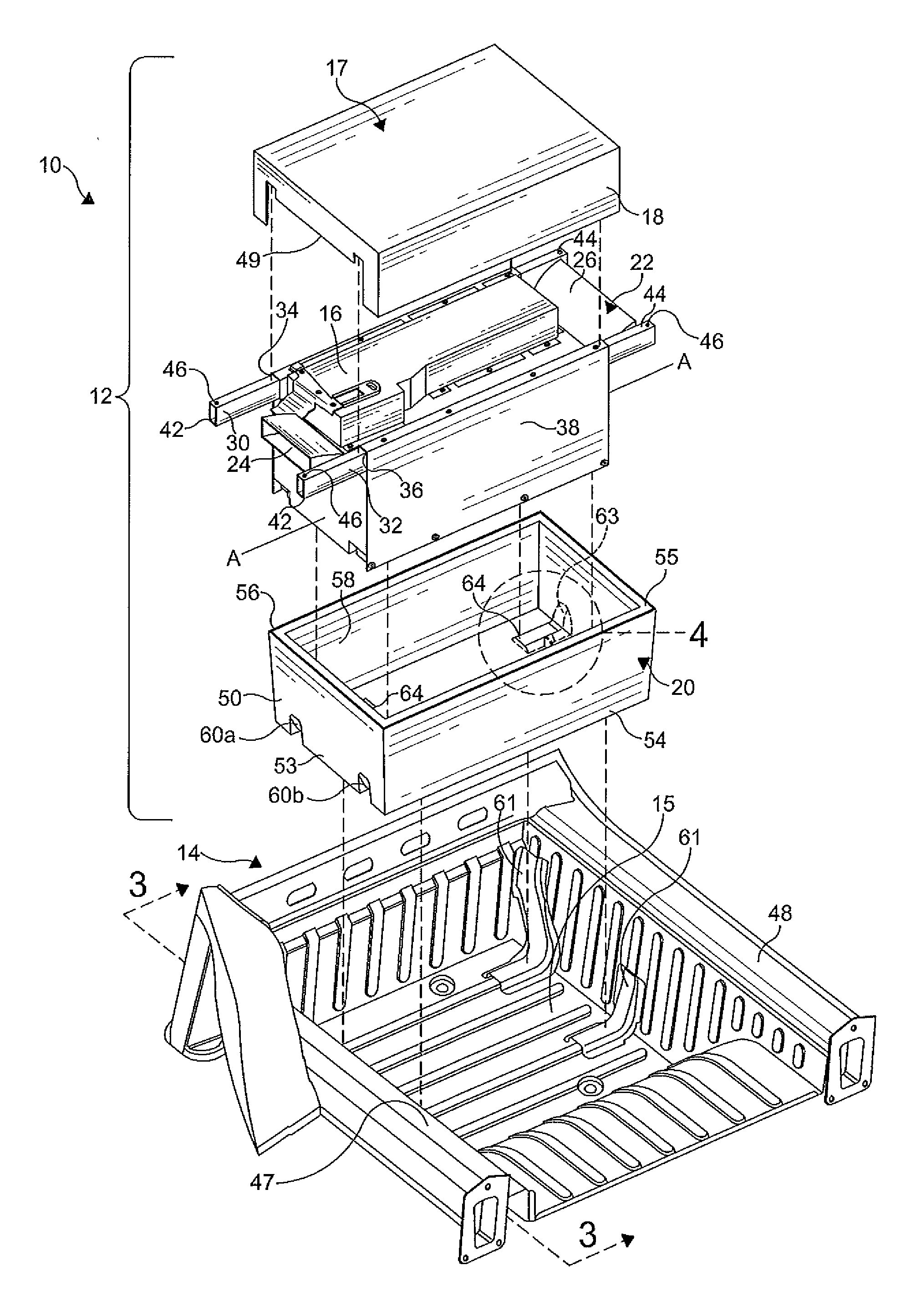
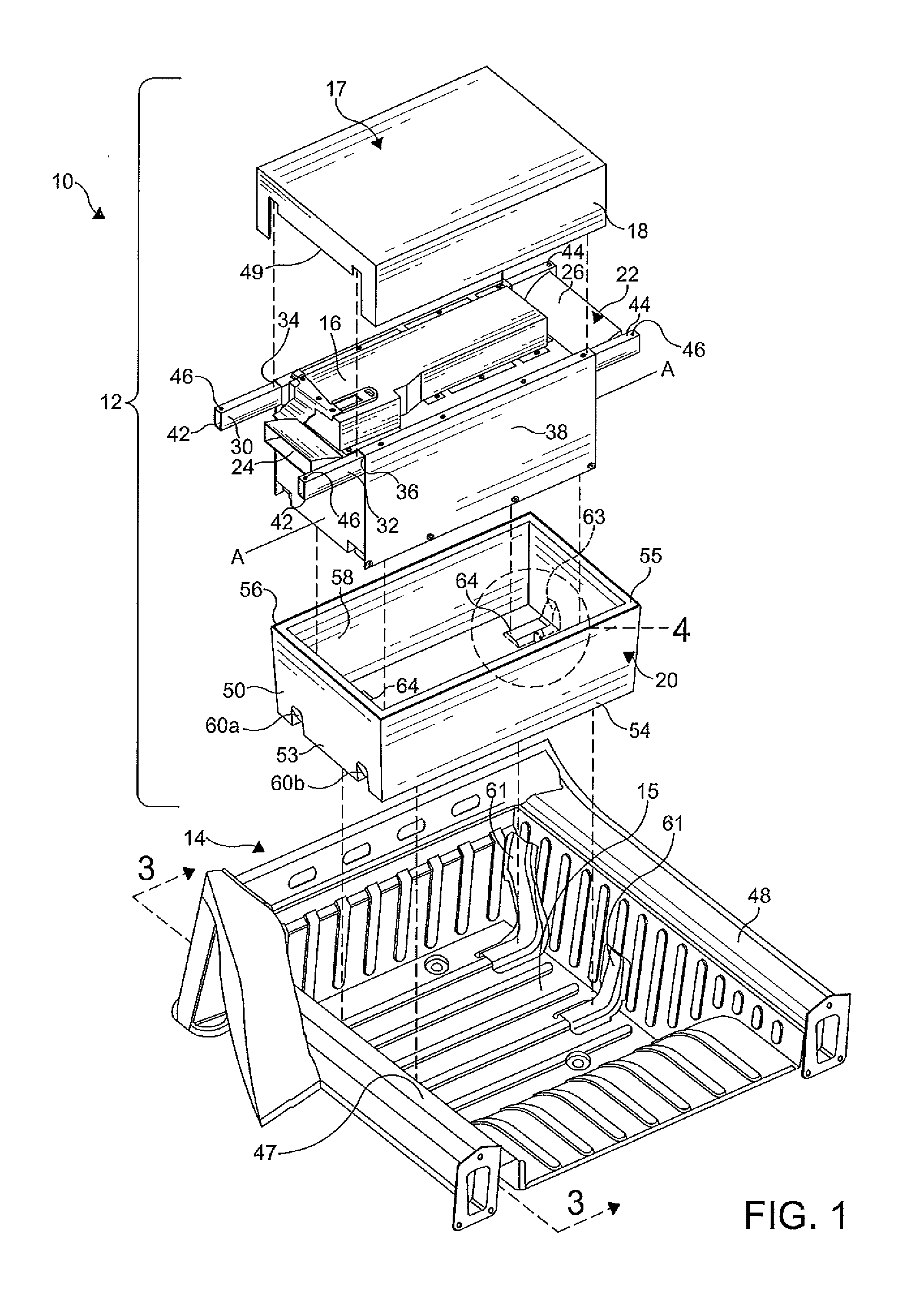
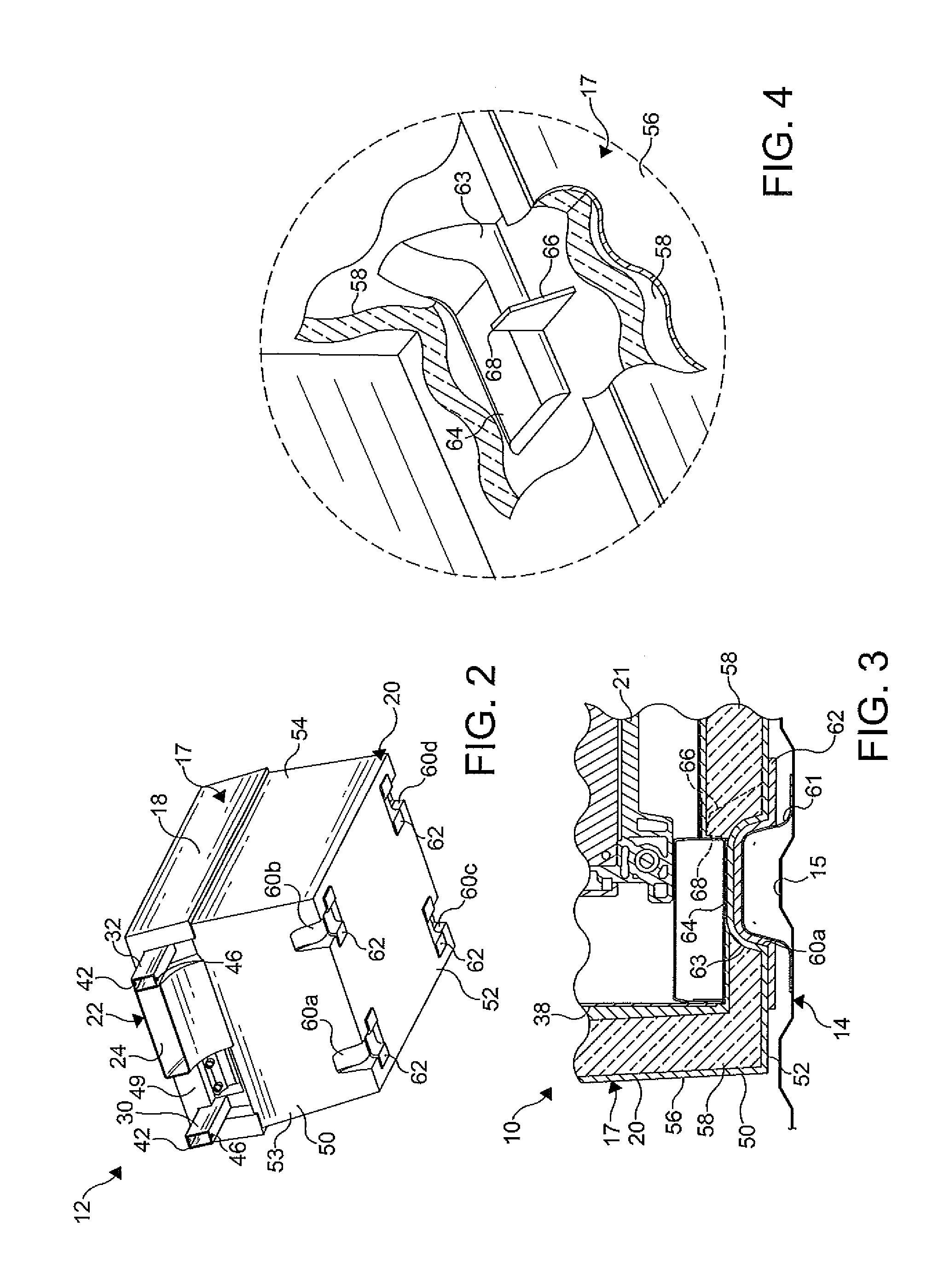
[0015]FIGS. 1 and 3 illustrate a mounting arrangement 10 for a battery pack 12 in a vehicle body 14 of a vehicle (not shown) according to an embodiment of the present invention. It is understood that the mounting arrangement 10 is not limited to use in a vehicle and can be employed in other applications utilizing the battery pack 12 as desired. The mounting arrangement 10 shown provides a desired stiffness and strength to withstand a minimum of thirty-five hertz (35 hz) vibration frequency for a first mode within the vehicle, and knee and shock loads of the vehicle. However, it is understood that the mounting arrangement 10 can have other vibration frequencies. As shown in FIG. 1, a compartmen...


PUM


Abstract

A mounting arrangement for a battery pack in a vehicle including the battery pack and a vehicle body, the battery pack including a housing having a hollow interior and a battery assembly disposed in the hollow interior of the housing, wherein the battery assembly includes at least one battery cell and a plurality of rails coupled thereto, and the vehicle body including support rails and a compartment formed therein to receive the battery pack therein, wherein the compartment of the vehicle body supports the housing and the support rails support the rails of the battery assembly to divide a vertical load of the battery pack.

Description

FIELD OF THE INVENTION[0001]The present invention generally relates to a battery pack, and more particularly to a mounting arrangement of the battery pack in a vehicle.BACKGROUND OF THE INVENTION[0002]A battery cell has been proposed as a clean, efficient and environmentally responsible power source for electric vehicles and various other applications. One type of battery cell is known as a lithium-ion battery cell. The lithium-ion battery cell is rechargeable and can be formed into a wide variety of shapes and sizes so as to efficiently fill available space in an electric vehicle. A plurality of individual lithium-ion battery cells can be provided in a battery pack to provide an amount of power sufficient to operate the vehicle. Typically, in order to provide a high power density in an efficient package, a large number of battery cells (often much greater than 10) is packaged within an individual battery pack.[0003]Various arrangements are employed to mount the battery pack within ...

Claims


Application Information

Patent Timeline
IPC IPC(8): H01M2/00H01M50/204H01M50/242H01M50/244H01M50/262
CPCB60K1/04H01M2/1083Y02T10/7011H01M10/345H01M10/0525Y02E60/10H01M50/204H01M50/262H01M50/242H01M50/244Y02P70/50
Inventor SCHWAB, LEO F.
Owner GM GLOBAL TECH OPERATIONS LLC
Why Eureka
Try Eureka