
Method and System of Measuring Toric Lens Axis Angle

a toric lens and axis angle technology, applied in the direction of optical axis determination, optical apparatus testing, instruments, etc., can solve the problems of increased cycle time, extra step, cycle time, etc., and achieve the effect of reducing the cycle time of inspection algorithm and cost efficien

Active Publication Date: 2011-11-03
BAUSCH & LOMB INC
View PDF5 Cites 4 Cited by
  • Summary
  • Abstract
  • Description
  • Claims
  • Application Information

AI Technical Summary

Benefits of technology

This patent describes a way to check the alignment of two parts (the posterior and anterior molds) when they are put together without measuring the alignment directly on the finished product (a toric lens). Instead, it measures the alignment first on a separate platform before putting them back together. This makes things easier and faster because we don't have to worry about checking for any mistakes at the same time. It also means that if there are any issues with the alignment, we can fix them more easily since we know where they are located already.

Problems solved by technology

The technical problem addressed in this patent text relates to improving the efficient measurement of the axis angle of toric lenses during production without increasing cycle time.

Method used


Image

  • Method and System of Measuring Toric Lens Axis Angle
  • Method and System of Measuring Toric Lens Axis Angle
  • Method and System of Measuring Toric Lens Axis Angle

Examples


Embodiment Construction

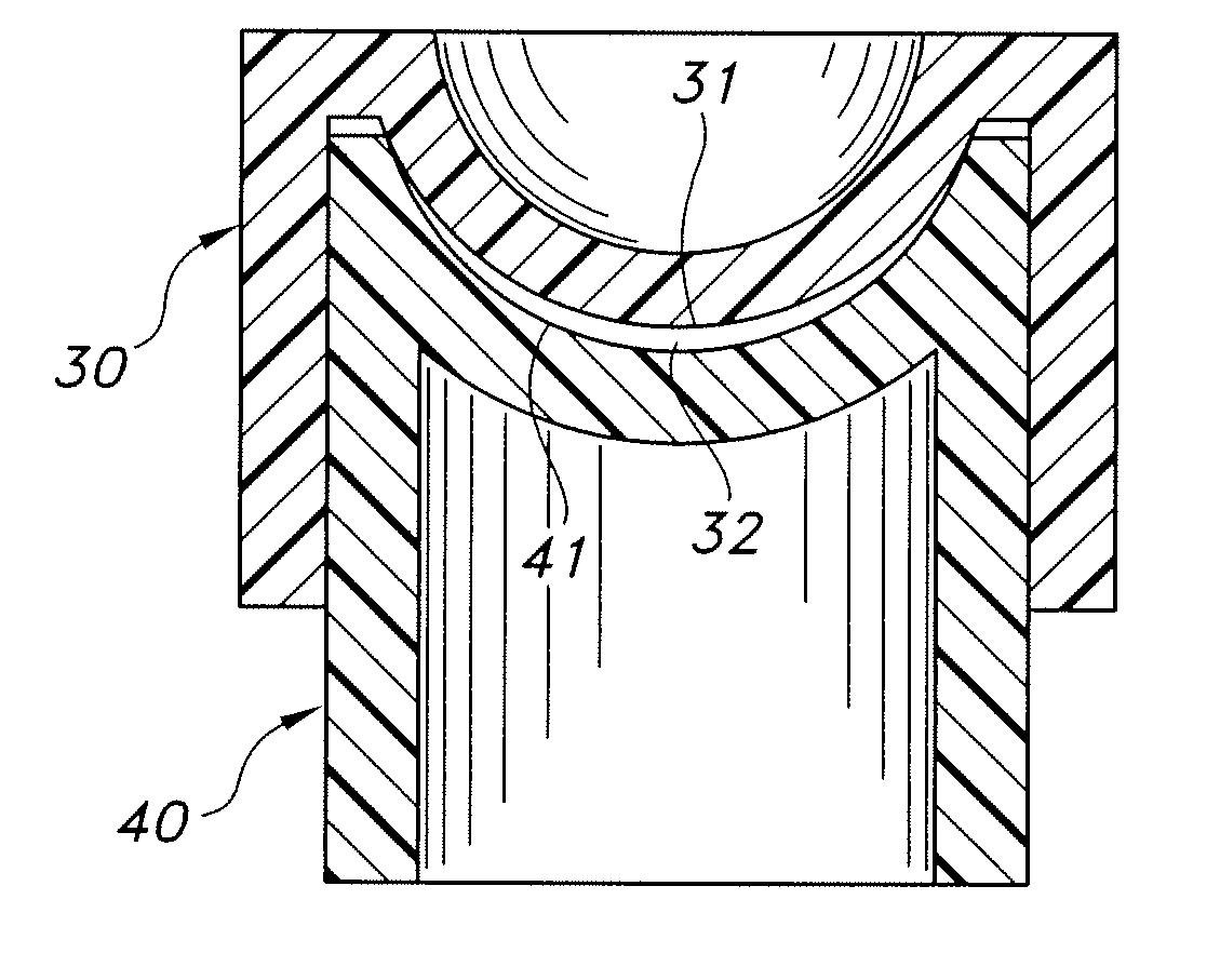
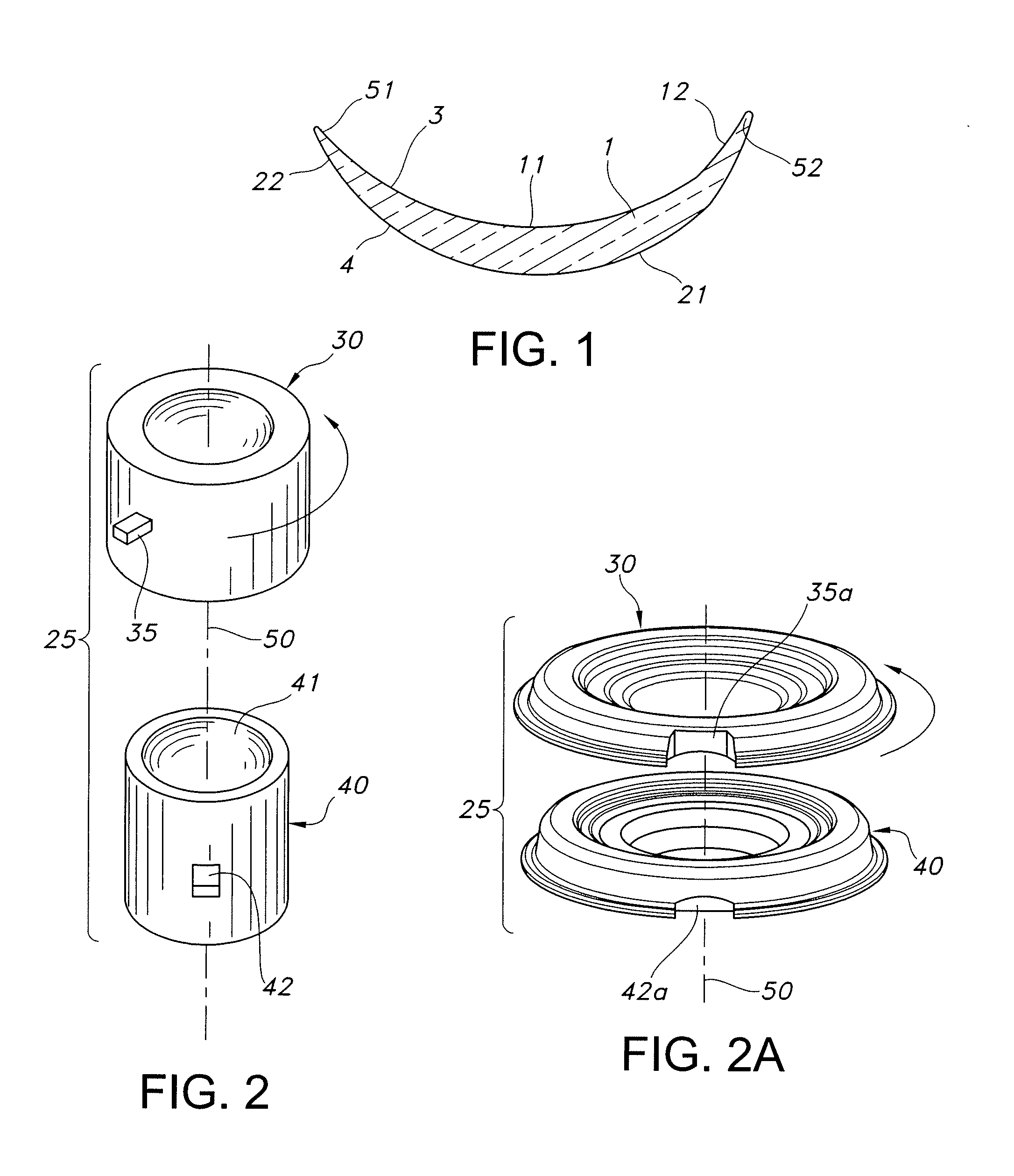
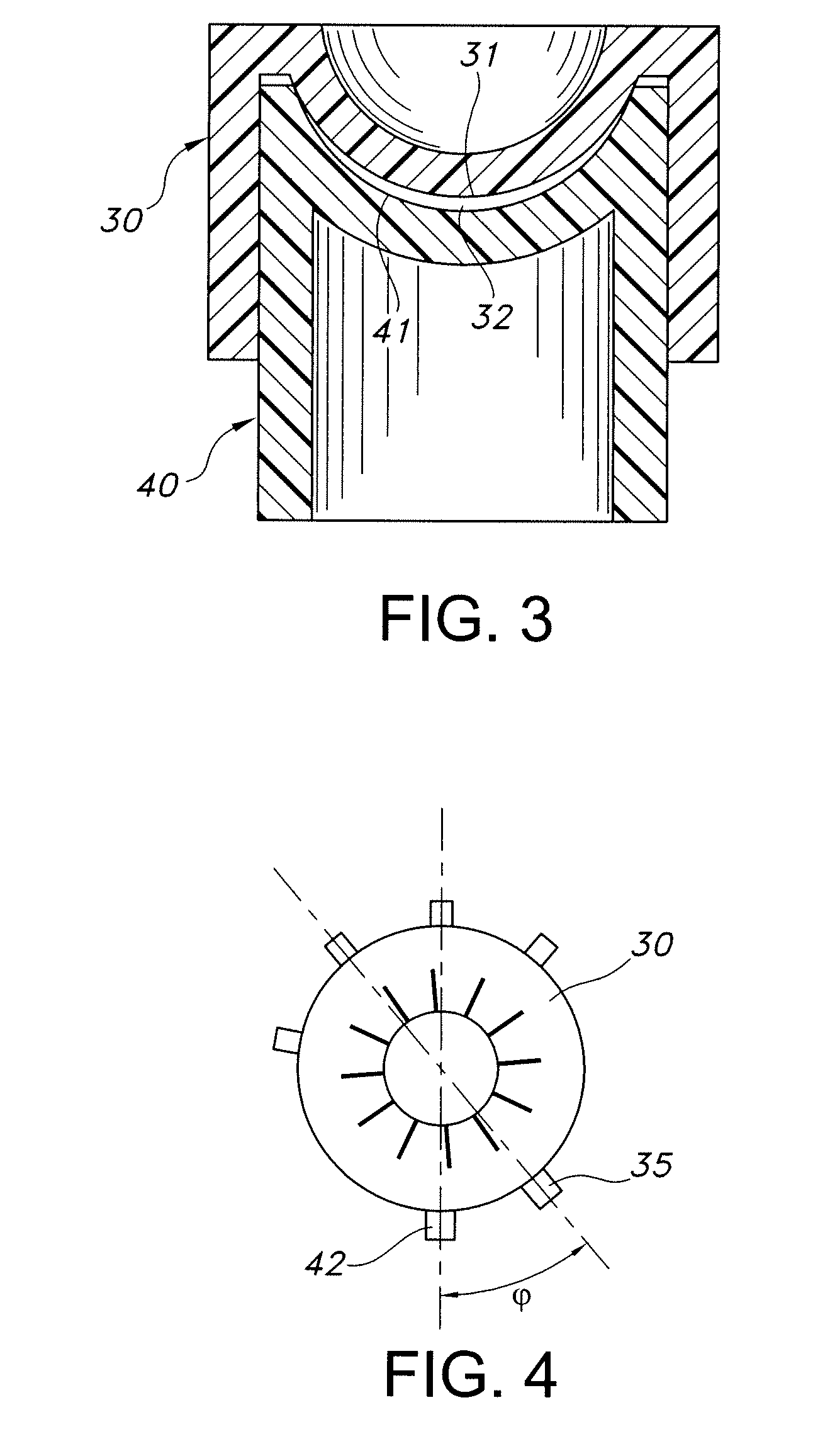
[0032]FIG. 1 schematically illustrates a representative toric contact lens 1 that may be produced herein. Central zone 11 of posterior surface 3 is toric, i.e., this zone has a toric surface that provides the desired cylindrical correction. Posterior surface 3 may optionally include at least one peripheral curve 12 surrounding the central toric zone 11. For the described embodiment, central zone 21 of anterior surface 4 is spherical, and the spherical curve is matched with central zone 11 to provide the desired spherical correction to the lens. Anterior surface 4 may optionally include at least one peripheral curve 22 surrounding central zone 21.

[0033]Lens 1 is provided with a ballast so that the lens maintains a desired rotational orientation on the eye. For example, as schematically shown in FIG. 1, peripheral section 51 may have a different thickness than an opposed peripheral section 52 of the lens periphery. As is known in the art, the ballast is oriented about an axis, and tor...


PUM

PropertyMeasurementUnit
Angleaaaaaaaaaa
Angleaaaaaaaaaa
Angleaaaaaaaaaa

Abstract

A method of measuring an axis angle of a toric contact lens including a posterior toric central zone having a cylindrical axis, and an anterior lens surface forming a ballast that has an axis of orientation offset from the cylindrical axis at a selected rotational angle is disclosed. The method involves (a) providing anterior and posterior mold sections including respective anterior and posterior mold cavity defining surfaces, wherein the posterior mold cavity defining surface includes a toric central zone and the anterior mold cavity defining surface is shaped to provide the ballast, the mold sections being alignable at multiple rotational positions; (b) providing a detectable feature on each of the anterior and posterior mold sections at a predetermined angular location with respect to the tonic and ballast axes thereof, respectively; (c) rotating the detectable feature of the posterior mold section relative to the detectable feature of the anterior mold section, wherein the detectable feature of the anterior mold section is a zero reference; and (d) measuring the axis angle between the detectable feature of the posterior mold section relative to the detectable feature of the anterior mold section after rotational displacement of the mold sections during toric contact lens formation.

Description


Claims


Application Information

Patent Timeline
Owner BAUSCH & LOMB INC
Learn More