Head mounted display and drive method thereof

Inactive Publication Date: 2011-11-03
BROTHER KOGYO KK
View PDF3 Cites 59 Cited by
  • Summary
  • Abstract
  • Description
  • Claims
  • Application Information

AI Technical Summary

Benefits of technology

[0010]According to the present disclosure, the drive part and the light source part starts an operation in response to a pressure detected by

Problems solved by technology

In this manner, the user can easily wear or remove the eyeglass-type HMD in which the display device is mounted on the eyeglass-type frame.
In this case, electricity is wastefully consumed.
There is also a case where when the user puts the HMD in his bag or the like,

Method used


Image

  • Head mounted display and drive method thereof
  • Head mounted display and drive method thereof
  • Head mounted display and drive method thereof

Examples


Example

[0027]Hereinafter, the present disclosure is explained in detail in conjunction with drawings.

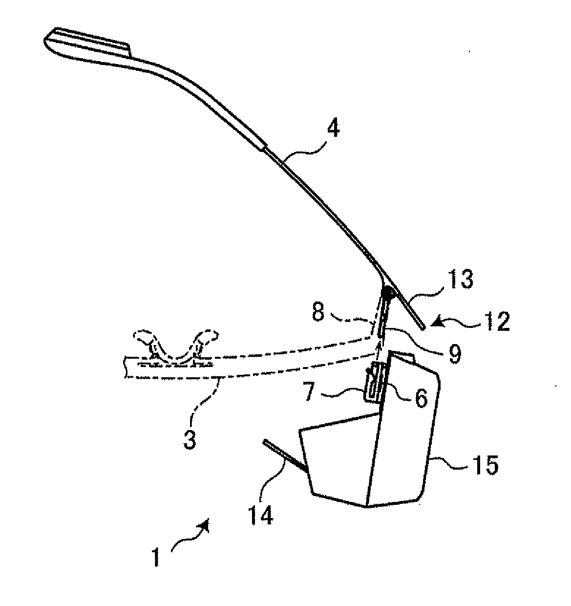
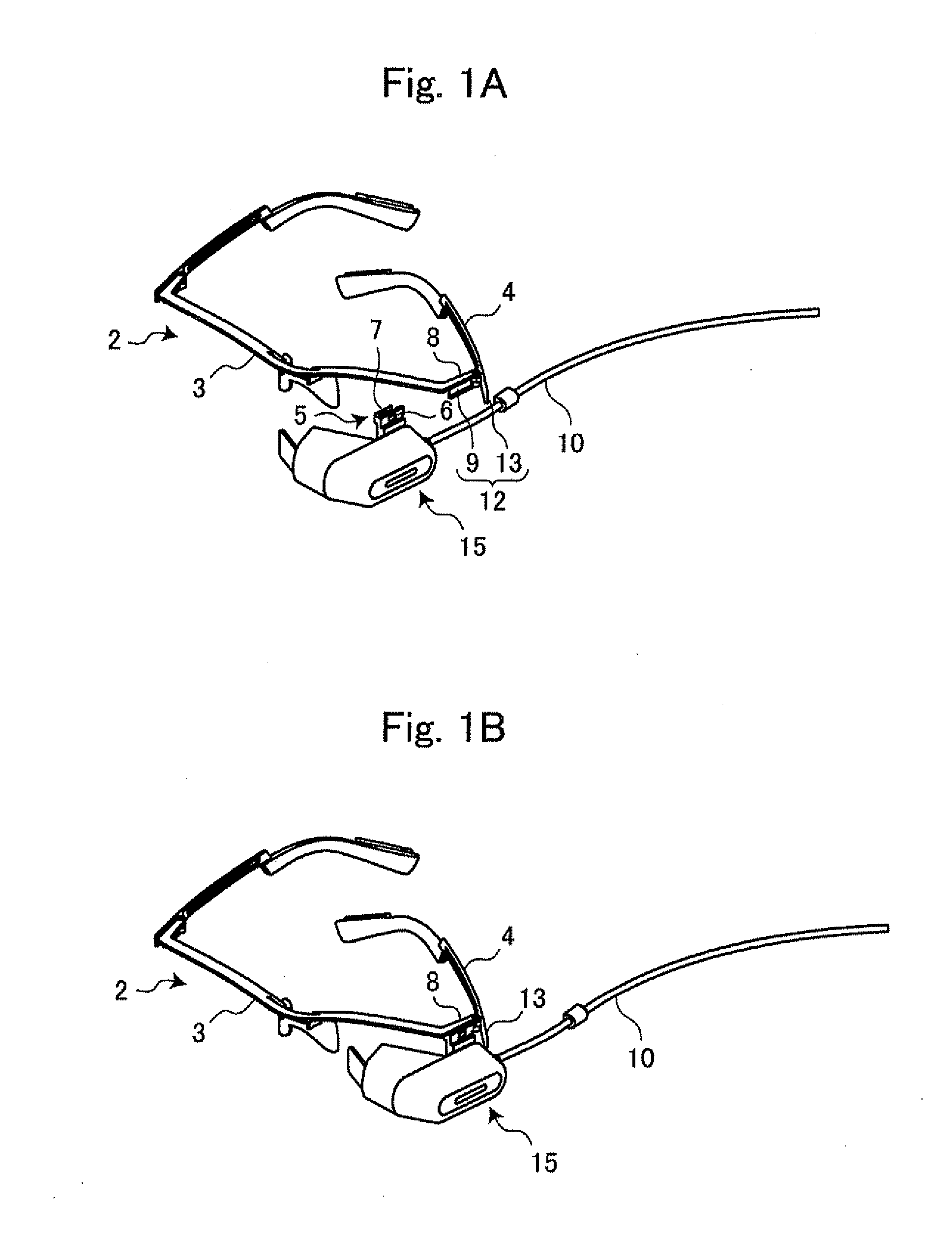
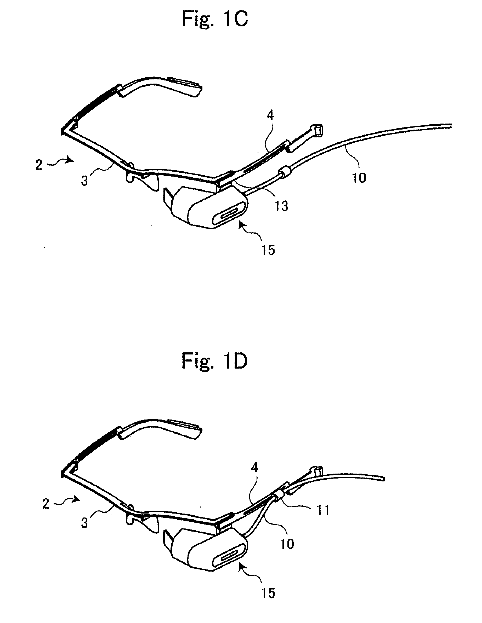
[0028]An HMD 1 which is in a state where a display part body 15 and an eyeglass-type frame 2 which constitute the HMD 1 are separated from each other is explained in conjunction with FIG. 1A. As shown in FIG. 1A, the display part body 15 projects a projection light for representing (forming) an image based on an image signal inputted through a connection line 10. The display part body 15 projects the projection light obtained by conversion on a retina of a user not shown in the drawing. The user can see a projection image by visually recognizing the projection light.

[0029]The eyeglass-type frame 2 includes a front frame 3 and wraparound endpieces 8 which are bent toward head sides of the user from the front frame 3. On a lower end of the wraparound endpiece 8, an extending part 9 which extends downward from the wraparound endpiece 8 is formed. On a distal end of the wraparound endpiece 8 on...


PUM


Abstract

A head mounted display includes a display device and a pressure detecting part. The display device includes an eyeglass type frame provided with temples which are connected to a front frame in an openable/closable manner, a light source part, a drive part and a control part. The pressure detecting part detects opening/closing of the temple with respect to the front frame. The control part controls a starting of the operation of the drive part and a starting of the operation of a light source part corresponding to magnitude of pressure detected by the pressure detecting part.

Description

CROSS-REFERENCE TO RELATED APPLICATIONS[0001]The present application is a Continuation-in-Part of International Application PCT / JP2010 / 050177 filed on Jan. 8, 2010, which claims the benefits of Japanese Patent Application No. 2009-007613 filed on Jan. 16, 2009.BACKGROUND OF THE DISCLOSURE[0002]1. Field of the Disclosure[0003]The present disclosure relates to a head mounted display which allows a user to observe a projected image in a state where a display device is mounted on an eyeglass-type frame.[0004]2. Description of the Related Art[0005]Conventionally, there has been known a head mounted display (hereinafter, referred to as “HMD”) with which a user can observe a video or an image while wearing the HMD on his head. With the use of the HMD, the user can enjoy a video such as a movie or an image in any place without selecting specific places. As the HMD, there has been known a goggle-type HMD which a user uses while wearing the HMD around his head using a band or the like and an ...

Claims


Application Information

Patent Timeline
IPC IPC(8): G06F3/038G09G5/00
CPCG02B27/0093G02B27/017G02C9/00G02B2027/014G02B27/0176
Inventor HAYAKAWA, KAZUHIRO
Owner BROTHER KOGYO KK
Why Eureka
Try Eureka